
English Русский
Български
Беларускі
Український
Српски
Hrvatski
Română
Polski
Slovenský
Magyar
  |  Articles  |  Sitemap  |  Contacts  |    |
Car maintenance Ford Car maintenance Hyundai Car maintenance Chevrolet Car maintenance BMW Car maintenance Audi Car maintenance Opel Car maintenance AvtoVAZ
VWmanual.ru


Main   Passat   Golf   Polo   Touareg   Tiguan   Sharan   Transporter   Others  
Tiguan 1 (2007-2015)

Electrical and electronic units and parts and their installation locations (VW Tiguan 1)

  • Main
  • Tiguan
  • Tiguan 1
  • Transmission
  • 6-speed automatic gearbox 09M
  • Electrical and electronic units and parts and their installation locations
            0


Electrical and electronic units and parts and their installation locations

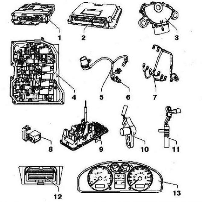
  • 1 - Automatic transmission control unit "J217". The control unit transmits and receives data from the data bus, can be checked by guided fault finding with -VAS 5051-
  • 2 - Engine control unit. The control unit sends and receives information via the data bus
  • 3 - Multifunction switch "F125" can be checked using guided fault finding with -VAS 5051-
  • 4 - Spool valve, components can be checked in guided fault finding mode with -VAS 5051-
  • 5 - Sensor wiring harness with transmission oil temperature sensor "G93"
  • 6 - Transmission oil temperature sensor "G93" can be checked using guided fault finding with -VAS 5051-
  • 7 - Solenoid valve wiring harness
  • 8 - Selector lever lock solenoid "N110". Installation location: The selector lever lock solenoid is located in the shift drive, can be checked using the guided fault finding with -VAS 5051-
  • 9 - Selector with Tiplronic switch "F189", the Tlptronic switch-F189- is a component of the gearshift drive, can be checked in the Guided Fault Finding mode using -VAS 5051-, if faulty, replace the gearshift drive
  • 10 - Gearbox input speed sensor "G182" can be checked using guided fault finding with -VAS 5051-
  • 11 - Gearbox output speed sensor "G195" can be checked using guided fault finding with -VAS5051-
  • 12 - Diagnostic connector
  • 13 - Automatic gearbox selector position indicator "Y6"


Automatic transmission control unit "J217" "arrow"
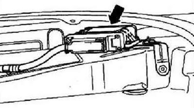


Automatic transmission control unit «J217» «arrow»


Location: The control unit is located on the front left wheel arch. To remove and install it, you need to remove the front wing liner.


Multifunctional switch "F125"
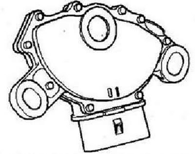


Multifunctional switch «F125»


Location: The multifunction switch is located on the top of the gearbox.

Switch block
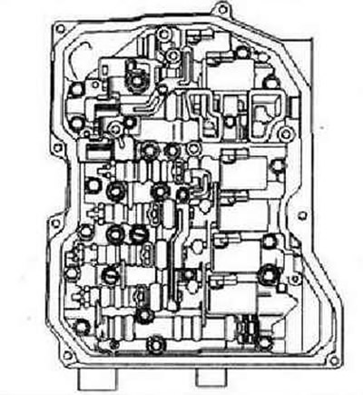


Switch block


Location: The electrohydraulic unit is bolted to the bottom of the gearbox housing and is covered by the gearbox oil pan. The distribution module contains the solenoid valves "N88" and "N89", as well as the pressure control valves "N90", "N91", "N92", "N93", "N₂82" and "N₂83".

Sensor Wiring Harness
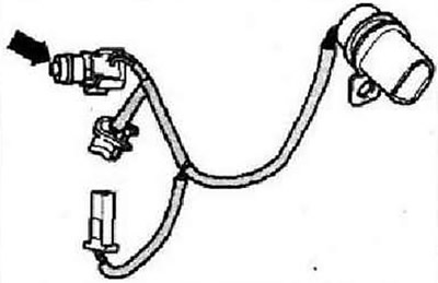


Sensor Wiring Harness


With built-in transmission oil temperature sensor "693" "arrow". Location: the wiring harness is attached to the distribution module of the gearbox.


Solenoid valve wiring harness
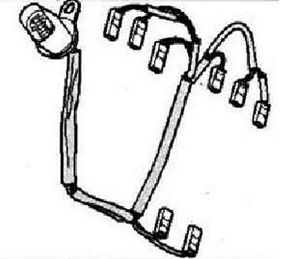


Solenoid valve wiring harness


Location: The wiring harness is attached to the transmission distribution module.

Gearbox Input Speed Sensor "G182" and Gearbox Output Speed Sensor "G195"
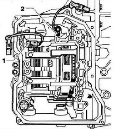


Gearbox Input Speed Sensor «G182» and Gearbox Output Speed Sensor «G195»


Location: sensors above the distribution module in the gearbox housing.
  • 1 - Gearbox Input Speed Sensor "G182"
  • 2 - Gearbox output shaft speed sensor "G195"

Diagnostic connector
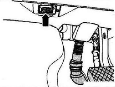


Diagnostic connector


Location: The "arrow" diagnostic connector is installed on the left under the trim on the driver's side.

Automatic gearbox selector position indicator "Y6"
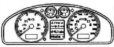


Automatic gearbox selector position indicator «Y6»


Location: in the instrument cluster.

This article is available at russian, bulgarian, belarusian, ukrainian, serbian, croatian, romanian, polish, slovak, hungarian
The text has been checked: Tarasov Ivan

Share information:

Previous articles
Letter designation, compatibility of units
Marking on the gearbox
Next articles
Removal the F125 multifunction switch
Overview of the switching drive
Checking the cable traction
Emergency release of the selector
Checking the gear shift drive
Gearbox Removal — 2.0L 147kW TSFI Engine Vehicles


Similar articles from other manuals for VW cars:
Electrical/electronic components and their installation location Passat B6 (2005-2010)
Conventional designations of the most important units and parts Golf 5 (2003-2008)
Electronic Engine Control (EPC) Polo 3 (1995-2003)
Electronic components and their installation locations on the… Touareg 1 (2002-2006)
Checking the crankshaft parts Sharan 1 (1995-2000)
Care of plastic parts Transporter T4 (1990-2003)
List of units and parts of the lubrication system Caddy 3 (2003-2010)
Link to this page in different formats


Visitor comments


No comments yet


How much will 26 + 17 =


Tiguan 1 
  • General information
  • Characteristics
  • Vehicle overview
  • Power unit
  • Petrol engine 1.4 BWK
  • Petrol engine 1.4 CAVA
  • Engine 2.0 (petrol)
  • Engine 2.0 (diesel)
  • Transmission
  • 6-speed manual gearbox 0A6
  • 6-speed automatic gearbox 09M
  • Drive shafts
  • Chassis
  • Front suspension
  • Rear suspension (2x4)
  • Rear suspension (4x4)
  • Air suspension
  • Wheels and rims
  • Brake system
  • Steering gear
  • Body
  • External equipment
  • Internal equipment
  • Electrical equipment
  • Power devices
  • Appliances and lighting
  • Communication systems
  • Heating and air conditioning
  • Electrical circuits
VWmanual.ru © 2016-2026 | Mobile version | News and articles | Sitemap: EN BG BY UA RS HR RO PL SK HU | Write message | Site search
Passat B2 • Passat B3 • Passat B4 • Passat B5 • Passat B6 • Golf 1, diesel • Golf 1, petrol • Golf 2, petrol • Golf 2 • Golf 3 • Golf 4 • Golf 5 • Polo 3 • Polo 4 • Touareg 1 • Tiguan 1 • Sharan 1 • Transporter T3 • Transporter T4 • LT 28 • LT 2D • Beetle • Caddy 3 •
Our website uses cookies to ensure functionality and convenience.