
| Designation | Detail |
| A | Battery |
| IN | Starter |
| WITH | Alternator |
| D | Egnition lock |
| E | Manual switch |
| F | Mechanical switch |
| G | Sensor, control device |
| H | Horn, double tone horn, fanfare horn |
| J | Relay, control unit |
| K, L, M, W, X | Signal lamps, lamps, lanterns |
| N | Solenoid valves, resistors, switches |
| ABOUT | Distributor |
| P, Q | spark plug tips, spark plugs |
| R | Radio |
| S | Circuit breakers |
| T | Plug connections |
| V | Electric motors |
Relays and electronic controls are usually shown with a gray background. Lines drawn against this background represent internal connections. They show how the relay and other electrical and electronic components and parts are connected to each other, as well as to the relay unit.
The number in the black square indicates the location of the relay in the relay and fuse box. On the indicated relay, its contacts are indicated. For example, if the contact is marked 17/87 in the diagram, then the number 17 is the designation of the terminal in the relay block, and 87 is the designation of the terminal of the relay itself or the switching relay.
The designation of the terminals is normalized by the industrial standard of Germany (DIN). The most important terminals are:
1. Terminal 30. This terminal is constantly powered by the battery. The wire insulation is usually red or red with colored stripes.
2. Terminal 31. It is connected to «weight» (-). Wires leading to «mass» (-), as a rule, have brown insulation.
3. Terminal 15. Voltage is supplied to it through the ignition switch. Current flows through these wires only when the ignition is on. The wire is usually insulated in green or green with colored stripes.
4. The X terminal also supplies current only when the ignition is on, but this circuit is broken if the starter is being actuated. This ensures that the entire battery voltage is supplied to the ignition system when the engine is started. All the most powerful current consumers are connected to this circuit. High beam lamps are also powered through this terminal. So. when the high beam is on and the ignition is off, it automatically switches to the parking light.
In the diagram, individual wires are indicated by numbers.
For example: 1.5
The digital designation corresponds to the cross section of the wires.
Wires connected to each other with detachable connections (plugs), in addition to the letter «T», denoting a detachable connection, have a digital combination.
For example: T2p - two-pin connector, T32 / 27 - connector with 32 pins, pin 27.
In the diagram, all consumers and switches are shown in the rest position. The changes in current flow that occur after the switch is actuated are explained using the example of a two-pole switch (see illustration 1.0):
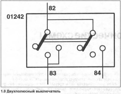
When switch 01242 is turned on in the first position, voltage from terminal 82 is supplied to terminal 83.
The jumper of the second position is then moved to the middle position without creating a connection. And only when pressed again and the second position is turned on, the jumper closes the circuit and supplies voltage through the internal connection from terminal 82 further through terminal 84. In this case, the internal connection on the switch is maintained due to the branch of terminal 83 through which power is supplied.
Attention! Fuses, starting with number 23, are indicated in the diagrams by the numbers 223, etc.
Wiring diagrams for VW Golf cars from November 2003
Due to the large volume, it is not possible to give all the schematic diagrams of models from different years. However, you can use the above diagrams, even if your car is of a different year of manufacture, because the changes, as a rule, concern only particulars.
Visitor comments