



Contents: Automatic transmission control unit ↓ Multifunctional sensor ↓ Distribution module ↓ Wiring harness, 8 pin ↓ Wiring harness, 14 pin ↓ 1st oil pressure sensor and 2nd oil…↓ Gearbox Input Speed Sensor and…↓ Tiptronic system sensor ↓ Diagnostic socket ↓
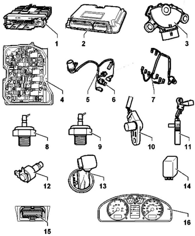
Fig. 3.73. Automatic transmission components installed on the vehicle: 1 – Automatic transmission control unit; 2 – engine control unit; 3 – Multifunctional sensor; 4 – distribution module; 5 – wire harness, 8-pin; 6 – working fluid temperature sensor; 7 – wiring harness, 14 pin; 8 – 1st oil pressure sensor; 9 – 2nd oil pressure sensor; 10 – gearbox input speed sensor; 11 – gearbox output speed sensor; 12 – selector lever locking electromagnet; 13 – Tiptronic system sensor; 14 – power supply relay class 50; 15 – diagnostic socket; 16 – selector position indicator
The automatic transmission components installed on the vehicle are shown in Figure 3.73.
Automatic transmission control unit
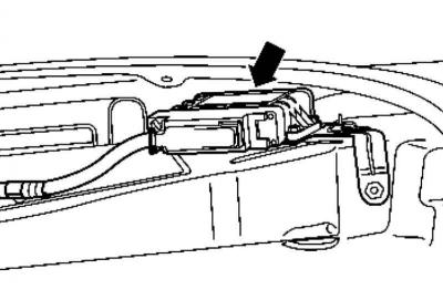
Fig. 3.74. Automatic transmission control unit
The control unit is located on the front left wheel arch (Fig. 3.74).
To remove or install it, you need to remove the front wing liner.
Multifunctional sensor
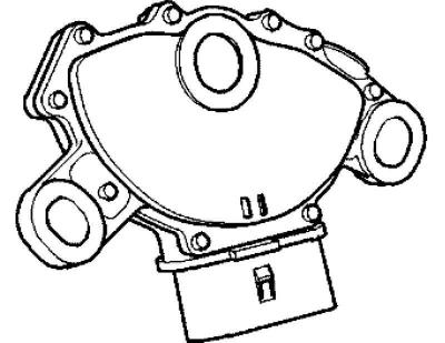
Fig. 3.75. Multifunctional sensor
The multifunctional sensor is located in the upper part of the gearbox (Fig. 3.75).
Distribution module
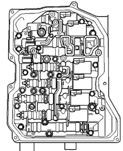
Fig. 3.76. Distribution module
The distribution module is screwed from below to the gearbox housing and is covered by an oil pan (Fig. 3.76).
The distribution module contains electromagnetic valves and pressure control valves.
Wiring harness, 8 pin
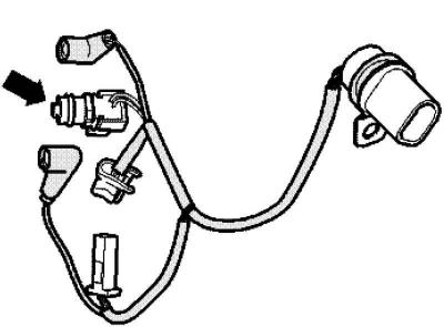
Fig. 3.77. Wiring harness, 8-pin
The wiring harness is attached to the gearbox distribution module (Fig. 3.77).
Wiring harness, 14 pin
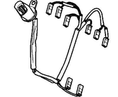
Fig. 3.78. Wiring harness, 14-pin
The wiring harness is attached to the gearbox distribution module (Fig. 3.78).
1st oil pressure sensor and 2nd oil pressure sensor
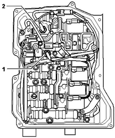
Fig. 3.79. Oil pressure sensors:
1 – 1st oil pressure sensor; 2 – 2nd oil pressure sensor
These sensors are not installed in all gearboxes (Fig. 3.79).
In gearboxes equipped with these sensors, they are located in the distribution module.
Gearbox Input Speed Sensor and Gearbox Output Speed Sensor
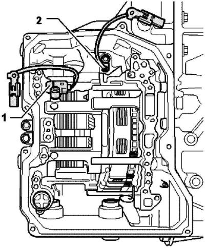
Fig. 3.80. Rotation speed sensors:
1 – input speed sensor of the gearbox;
2 – gearbox output speed sensor
The sensors are located above the distribution module in the gearbox housing (Fig. 3.80).
Tiptronic system sensor
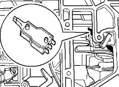
Fig. 3.81. Tiptronic system sensor
The Tiptronic system sensor is built into the gearbox control lever (Fig. 3.81).
On vehicles with a multi-function steering wheel, the steering wheel buttons and their wiring must also be checked.
Diagnostic socket
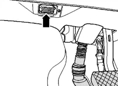
Fig. 3.82. Diagnostic connector
The diagnostic connector is installed on the left under the trim on the driver's side (Fig. 3.82).
Visitor comments