



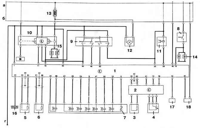
Fig. 4-61. Electrical diagram of the hydromechanical transmission control system:
1 — electronic control unit of the hydromechanical gearbox;
2 — KSUD controller;
3 — engine crankshaft speed sensor;
4 - Potentiometric accelerator pedal position sensor;
5 - vehicle speed sensor;
6 — hydromechanical gearbox speed sensor;
7 — hydromechanical transmission oil temperature sensor;
8 - brake light switch;
9 - Multifunctional sensor;
10 — starter and reverse light interlock relay;
11 — electromagnetic lock of the selector lever;
12 — gear shift indicator lamp;
13 - fuse no. 13;
14 - brake light malfunction indicator lamps;
15 — warning lights for reversing light malfunction;
16 — diagnostic socket;
17 — electromagnetic clutch of the air conditioning compressor;
18 - software speed controller.
a — "+" battery;
b — "+" after ignition on;
in — "+" of the starter (terminal "50");
g — mass.
The original article is available at www.VWManual.ru
Visitor comments