
20-pin connector, marked on the diagram as T20s
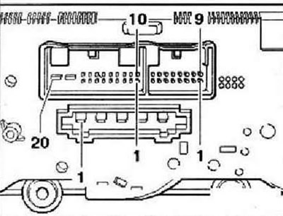
- 3 - Temperature sender for central vent -G191-
- 5 - High pressure sender -G65-
- 7 - CAN low bus
- 8 - CAN high bus
- 12 - Heating of the right seat (option)
- 13 - Left seat heating (option)
- 15 - Terminal 75 for connecting seat heating (option)
- 16 - Air conditioner compressor regulating valve -N280-
- 19 - Terminal 30A
- 20 - Terminal 31
16-pin connector, marked on the diagram as T16e
- 1 - Temperature flap control motor -V68-, temperature increase
- 2 - Evaporator temperature sender -G308- or evaporator outlet air temperature sender -G263-
- 4 - Footwell air duct temperature sender -G192-
- 5 - Temperature flap control motor potentiometer -G92-
- 7 - + 5 V for temperature flap control motor potentiometer -G92-
- 8 - Ground for temperature flap control motor potentiometer -G92-, center air duct temperature sender -G191-, footwell air duct temperature sender -G192- and evaporator temperature sender -G308- or evaporator outlet air temperature sender -G263-
- 9 - Recirculation flap control motor -V113-, opening
- 10 - Recirculation flap control motor -V113-, closing
- 11 - Temperature flap control motor -V68-, temperature reduction
- 16 - +5V
5-pin connector, marked on the diagram as T5
- 1 - 3rd fan speed
- 2 - 2nd fan speed
- 3 - 1st fan speed
- 4 - 4th fan speed
- 5 - Terminal X
Visitor comments