
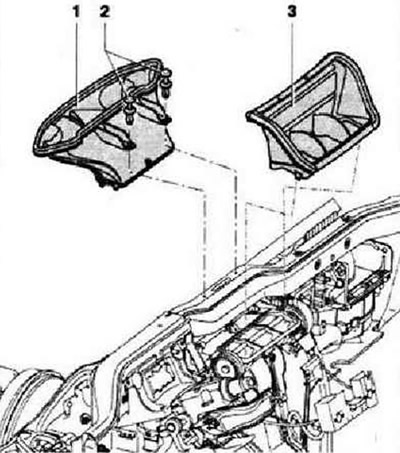
Instruction: To improve access (depending on engine variant) it is necessary to additionally remove some parts, for example, the engine cover. Remove front panel. Unclip retainers -2- and remove defroster air duct -1- from heater and air conditioner module. Remove the air duct part -3- from the heater and air conditioner module. Remove carrier frame. Remove the air ducts for the leg area on the left and right.
Position drip tray -VAS 6208- under engine. Mark hoses -1-.
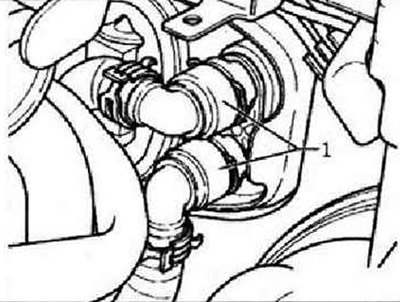
WARNING: Avoid burns from hot liquid.
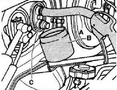
Clamp coolant hoses -1- with hose clamps for hoses up to Ø 40 mm -3093- and remove coolant hoses from heat exchanger. Push the short hose -A- onto the top connection of the heat exchanger. Place a container -B- under the lower fitting -C-. Connect the blow gun to the heat exchanger connection and carefully blow out any remaining coolant. Spread a waterproof film and absorbent paper on the fabric floor of the car.
Instruction: Write down the length and location of the unscrewed bolts to facilitate subsequent assembly.
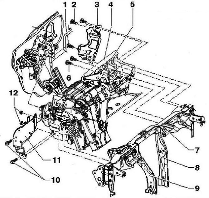
- 1 - Bolt, 4.5±0.7 Nm
- 2 - Bolts, 2 pcs., 4.5±0.7 Nm
- 3 - Cable clamp
- 4 - Heater removal. Cable ties and other means of fastening wiring harnesses, removed or cut when dismantling the climate control module, must be installed in their original places during assembly. wiring harness "heater" removed together with the heater module. Tunnel mounting supports -8- and -9- are welded to carrier frame -7-. Remove carrier frame. Disconnect the electrical connectors from the heater. Remove screws -6- from bracket -5-. Unscrew bolts -10-, unscrew nuts -12- and remove bracket -11-. Remove screws -1- and -2- from cable holder -3-.
Instructions: Cable ties and other means of fastening electrical wiring harnesses, removed or cut during dismantling, must be installed in their original places during assembly. To access the bolt -1-, the heater on the driver's side must be slightly moved away from the bulkhead. When removing the heater, make sure that both hoses leading to the heat exchanger do not kink at the edges of the openings in the bulkhead of the plenum box and soundproofing tray and are not damaged. To avoid damage to the wires, do not tighten the wiring harnesses too much.
Take out the heater.
Installation is carried out in the reverse order. When installing the heater, a second mechanic must pull both hoses for the heat exchanger from the engine compartment through the sealing collar, Fill in coolant.
- 5 - Bracket
- 6 - Bolts, 8 Nm
- 7 - Bearing frame
- 8 - The right post is rigidly fastened to the supporting frame
- 9 - The left rack is rigidly fastened to the supporting frame
- 10 - Bolts, 2 pcs., 9±1.3 Nm
- 11 - Bracket
- 12 - Nut, 2 pcs., 9±1.3 Nm
Seal between heater and engine compartment
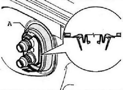
Instructions: When assembling, pay attention to the position of the sealing collar -A-.
Visitor comments