
Removing
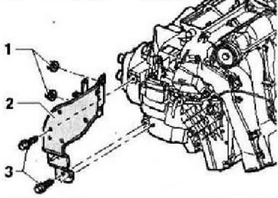
Remove the left legroom air duct. Remove the footwell trim on the driver's side. Remove data bus diagnostic interface -J533-. Remove bolts -3- (9±1.3 Nm). Do not loosen nuts -1-. Do not remove bracket -2-.
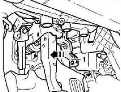
Slide bracket in direction of brake pedal -arrow- and secure with cable tie.
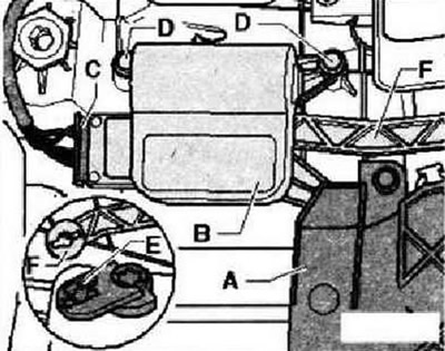
It is recommended to mark the connector -C- for the actuator motor, so as not to confuse it with other similar connectors in the future. Unplug connector -C- at temperature flap control motor -V68-. Remove cover -A-. Unscrew securing bolts -D- 1.4 Nm and remove temperature flap control motor -V68- -B-. Detach motor lever -E- from connecting rod -F-.
Installation
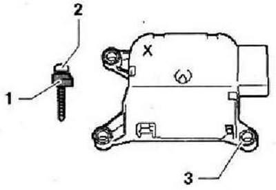
Note: Upgraded actuator motors are marked with -X-
For better fastening, use the button head screw -N 103 254 01-, which must be shortened by = 2 mm. To do this, for example, use side cutters to cut off the retaining lug -1- from the old temperature flap motor -V68-.
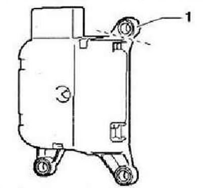
Fix a new one, marked with a sign "X", the temperature flap control motor -V68- with the help of the screw -2- with the cut-off eyelet -1- shortening the shaft to the fan housing through the eyelet -3-.
Instructions: After installation, check the operation of the left temperature control flap. Using tester -VAS 5051B- (or subsequent model) perform a basic installation.
Visitor comments