



Contents: Removal ↓ Installation ↓
The elements of the immobilizer are shown in Fig. 12.34.
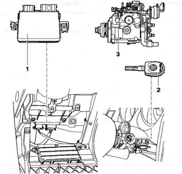
Fig. 12.34. Immobilizer elements:
1 - Immobilizer control unit; 2 - Transmitter integrated into the key; 3 - Fuel cut-off control unit on the high-pressure fuel pump.
Removal
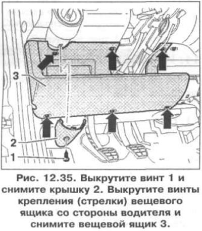
1. Unscrew screw 1 and remove cover 2 (fig. 12.35). Remove the mounting screws (arrows) of the glove box on the driver's side and remove glove box 3.
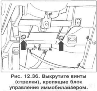
2. Remove the screws (arrows) securing the immobilizer control unit (fig. 12.36).
3. Disconnect the wiring connectors (arrows) from the immobilizer control unit (fig. 12.37).
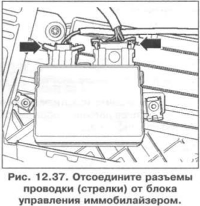
4. Remove the immobilizer control unit.
Installation
5. Installation is carried out in the reverse order of removal.
[The original article is available on the website vwmanual.ru]
Visitor comments