



Removing the heat shield
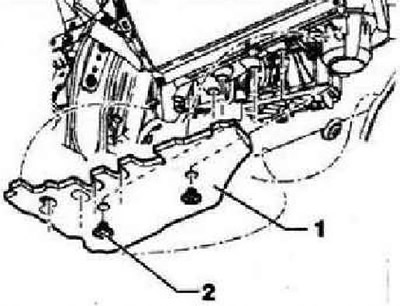
Release plastic screws -2- and remove heat shield -1-.
Installing the seal between the heater and the engine compartment
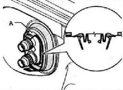
Insert seal between heater -A- and engine compartment first into bulkhead and then onto heat exchanger.
Instructions: To ensure that moisture from the engine compartment does not penetrate into the passenger compartment, the installation of the seal must be given due attention.
Removing fresh air blower -V2-
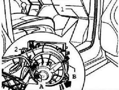
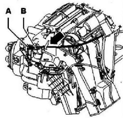
The fresh air blower -V2- is removed from the footwell side of the front passenger. Remove the heat shield from the heater. Unplug connector -A- from fresh air blower -V2-. Loosen screw -B- (if available) on fresh air blower housing -V2- (1 Nm). Unlock catch -2- and remove blower -V2- in direction of -arrow-.
Removing and installing ballast resistor for fresh air blower with overheating protection -N24-
8WARNING: Beware of burns. The ballast resistor of the fresh air blower with overtemperature protection -N24- may be hot. Before removing the ballast resistor for the fresh air blower with overtemperature protection -N24-, wait until it has cooled down.
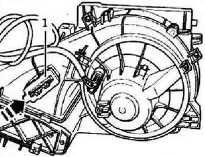
Remove the heat shield from the heater. Disconnect connector -A- from ballast resistor -N24-. Press clip in -direction of arrow- and pull fresh air blower ballast with overheating protection -N24- out of heater housing.
Removing and installing the cabin filter (anti-dust and anti-allergic)
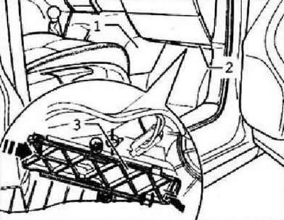
Remove footwell trim -1- on passenger side. Remove heat shield -2- from heater. Detach cover -3- by sliding it in the direction of the arrow. Remove the filter from the heater downwards.
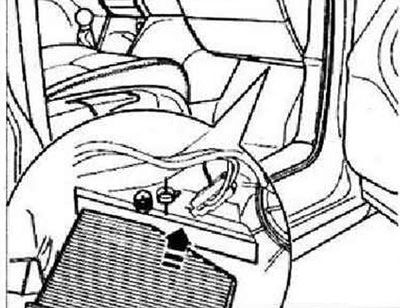
Installation is carried out in the reverse order.
Instructions: Install the filter in the correct position.
Removal and installation of deflectors from outside the driver and the forward passenger
Instructions: Removing the deflectors on both sides is done in the same way. In order not to damage the front panel, when dismantling, use spacers under the tool.
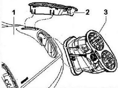
Detach side window vent -2- from dash panel -1-. Using wedge -3409-, remove air vent -3- from dash panel.
Removal and installation of the left and right air ducts to the rear passenger footwell
Instructions: The removal of air ducts on both sides is carried out in the same way.
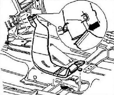
Remove the driver's seat or front passenger's seat. Remove center console. Raise the floor covering, disconnect the air duct from the floor and disconnect it from the heater.
Removal and installation of the right footwell air duct
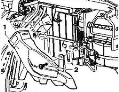
Remove storage box. Unscrew bolt -2- (1.5±0.2 Nm) and remove the right air duct -1-.
Removal and installation of the left footwell air duct
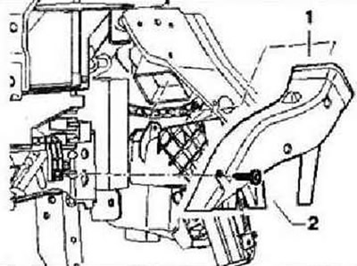
Remove the footwell trim on the driver's side. Unscrew bolt -2- (1.5±0.2 Nm) and remove the left air duct -1-.
Removal and installation of the block of rotary regulators of a heater and forced ventilation
Instruction: The rotary control unit consists of two separate parts. Before removing the unit, set the rotary controls to the following positions: heater control to position "cold", fan to position "0", airflow direction "to the feet".
Remove trim for heater and air conditioner control panel. Remove screws -2- (4,2x45) and -3- (4,2x16) and remove the control unit -1- from the center console.
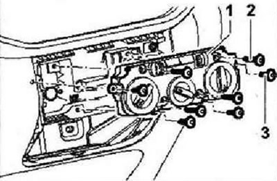
Tightening torque for screws -2- and -3-: 1.5±0.2 Nm. Detach connector lock -A- by sliding it in direction of arrow -1-. Press lock on connector -B- in direction of -arrow 2- and remove connector -C-. Unclip connector -D- and remove connector -D-.
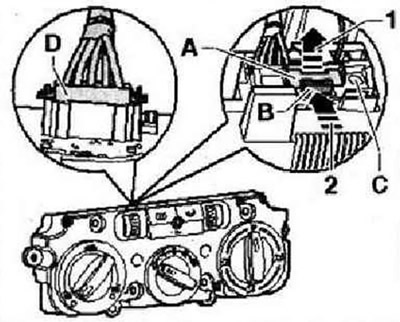
Instructions: The figure shows the version with "climate control unit Climatic". Disconnecting the connectors is done in the same way in all cases.
Connectors on the block of regulators of the heater and forced ventilation
The location of the contacts in the connectors on the rear wall of the heater and supply ventilation control unit (16-pin connector is not used).
5-pin connector, marked on the diagram as T5
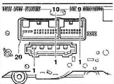
- 1 - 3rd fan speed
- 2 - 2nd fan speed
- 3 - 1st fan speed
- 4 - 4th fan speed
- 5 - Terminal X
20-pin connector, marked on the diagram as T20s
- 3 - Actuator motor for fresh air and air recirculation flaps -V154-
- 6 - Actuator motor for fresh air and air recirculation flaps -V154-
- 7 - Additional air heater control unit -J604-
- 8 - Rear window
- 11 - Driver seat heating control unit -J131-
- 15 - Front passenger seat heating control unit -J132-
- 16 - Terminal 75 for connecting seat heating (option)
- 18 - Terminal 30
- 19 - Terminal 15
- 20 - Terminal 31
Removal and installation of a flexible shaft to adjust the distribution of air flows
Remove tape recorder. For vehicles without a radio, remove the center dash panel trim. Remove storage box. Move the flexible shaft to the following position: turn the air distribution control knob -1- until until you can see where the shaft -2- is attached to the drive mechanism -3-.
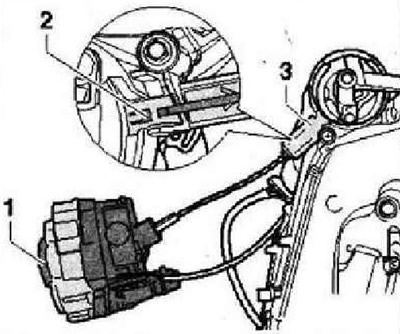
Remove the block of rotary regulators of a heater and forced ventilation. In the center console, unlock the latch by pressing it in the direction of the arrow. Remove flexible shaft from adapter -2-.
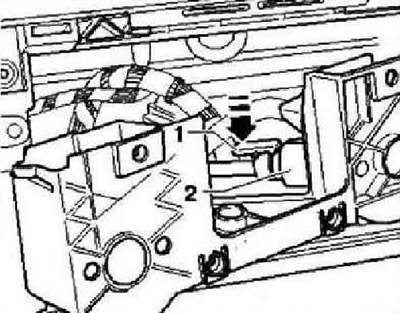
Instruction: When installing the flexible shaft, the adapter and rotary controls of the heater and fresh air must be in a certain position. Otherwise, these controls will not work properly.
Examination
Flexible shaft for controlling air dampers. Turn on the maximum fan speed. If in position "defrosting" all air is directed through the defrost vents and not into the footwell, then the flexible shaft is installed correctly. Otherwise, the flexible shaft must be disconnected from the adapter. Connect the heater and fresh air controllers to the adapter and turn the knob of the air distribution regulator by 180°. Then reattach the flexible shaft. Repeat check.
Removing and installing the temperature control damper cable
Remove the block of rotary regulators of a heater and forced ventilation. In the center console, detach the fastener -1- of the track sheath -2- and remove the cable sheath from the seat. Detach cable ball -3- from drive lever -4-.
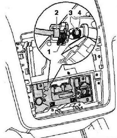
Remove the footwell trim on the driver's side. Detach cable from temperature control flap -A- and from heater -B-.
Removing and installing fresh air and recirculation flap control motor -V154-
Note: It is not allowed to change the position of the recirculation damper.
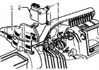
Remove storage box. Remove cover -1-. Disconnect connector from fresh air and recirculation control motor -V154- -2-. Remove electric motor -VI54- -2-.
Visitor comments