
Checking procedure
Measurements should be taken with the supports and roller arms removed.
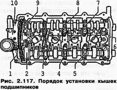
Insert camshaft and screw on bearing caps 3, 5 and 7 (pic. 2.117).
Intake camshaft
Position the universal holder with a dial indicator on the cylinder head, as shown in Figure 2.118.
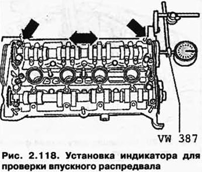
Axial clearance, wear limit: max. 0.20 mm.
Exhaust camshaft
Position the universal holder with a dial indicator on the cylinder head, as shown in Figure 2.119.
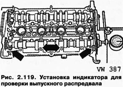
Axial clearance, wear limit: max. 0.20 mm.
Visitor comments