



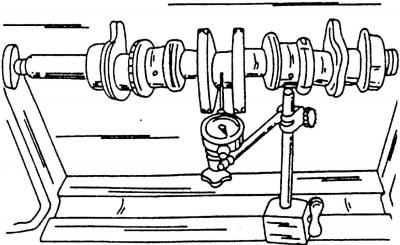
Fig. 442. Measuring crankshaft runout
Clamp the crankshaft in a lathe (Fig. 442) or clamp both journals of the shaft in prisms and measure the runout on the middle journal using an indicator. The runout should not be more than 0.06 mm. Otherwise, the shaft should be replaced. At present, there is no way to straighten the crankshaft.
Measure the runout of the main bearings and connecting rod bearings if the car with this shaft already has a high mileage. The car service uses for this "Plastigage" — plastic wire, however, as experience shows, it can be quite difficult to acquire. If you do not have the opportunity to acquire such a "measuring wire", then the same operation can be done in another way, which is described below. If you take measurements using "Plastigage", then proceed as follows:
- clean the bearing shells thoroughly and place them in the bearing beds of the cylinder block or in the connecting rods. Insert the "nose" of the bearing shells well into the guides;
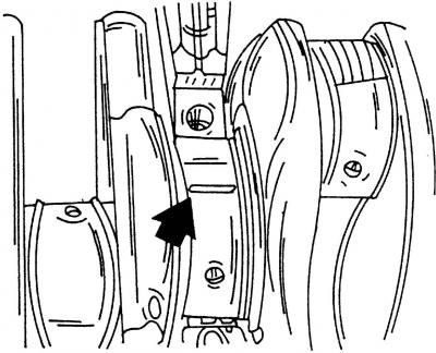
Fig. 443. Place a piece of wire "Plastigage" in the direction shown on the bearing journals
- put a piece of each "Plastigage" on the journal of each main bearing (fig. 443, shown by arrow) and install the main bearing cap with the bearing shells inserted. Tighten the bolts to a tightening torque of 65 N·m. After this, do not rotate the shaft any more;
- to check the clearances of the connecting rod bearings, place the connecting rod on the crankshaft journal and place it "Plastigage" on the upper part of the crankshaft journal. Install the bearing cap with the liner (again pay attention to the correct position of the "guide noses") and tighten the nuts to a tightening torque of 30 N·m. Since the shaft can no longer be turned, the measurements are carried out on two connecting rod bearings located at BDC;
- unscrew the caps on the main bearings; on the connecting rod bearings, unscrew both caps one by one;
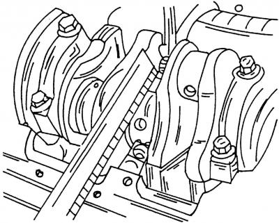
Fig. 444. Measuring flattened wires "Plastigage" using a measuring ruler
- using the measuring ruler included in the kit "Plastigage", measure the crushed strips of material at the widest point, placing a ruler on the plastic strips (Fig. 444). If this value exceeds 0.17 mm for main bearings or 0.12 mm for connecting rod bearings, then new bearing shells should be installed, taking into account whether or not the journals have been previously ground.
If you don't have plastic wire "Plastigage", and you yourself have some experience with such measurements, then the runout of the main and connecting rod bearings can be measured in the manner described below, which will allow you to draw the appropriate conclusions.
Install the bearing caps with the inserted bearing shells into the cylinder block and tighten the bolts to 65 N·m. Be sure to ensure that the shells are installed in their original positions. If connecting rod bearings are being measured, insert the shells into the connecting rods and connecting rod caps and tighten the caps with the old nuts to 30 N·m.
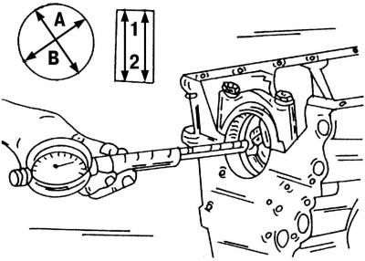
Fig. 445. Measuring the diameter of inserted bearing shells using an indicator. Measurements are taken in direction A and B, as well as in direction 1 and 2
Measure the bearings one by one - measurement diagram in Fig. 445. Pay particular attention to the direction of measurements A and B, as well as measurement locations 1 and 2. Record the measurement results for each individual bearing.
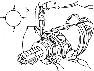
Fig. 446. Measuring the diameter of the main bearing journals. Take measurements at the locations shown by the arrows. The connecting rod bearing journals can be measured in the same way
Measure the diameter of each bearing journal in turn with a micrometer. Again, pay attention to the measurement locations indicated by arrows in Fig. 446. Record the measurement results for each bearing journal.
Subtract the bearing diameter measurement results from the inner diameter of the bearing holes. As a result, you will get the runout of the main and connecting rod bearings, the value of which should correspond to the values specified above.
To check the runout of the connecting rod bearings, rotate the crankshaft and measure the next two connecting rod journals as described.
[The original text is available on the portal www.VWmanual.ru]
Visitor comments