
- disconnect the terminal from AB «–», then «+»;
- remove AB;
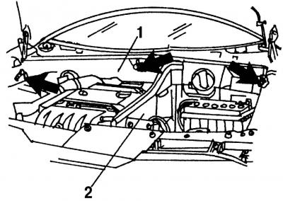
Pic. 18. AB removal: 1 - air duct casing; 2 - partition
- remove the battery compartment baffle (pic. 18);
- putting the front of the car on supports, remove the engine protection;
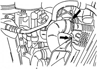
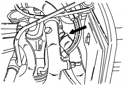
Pic. 358. Removing the charge air hose and air supply deflector. The arrows show the points of disconnection
- disconnect the right air hose (pic. 358) from the charge air cooler. Having unscrewed two bolts, remove the air supply deflector to the charge air cooling radiator;
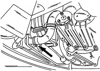
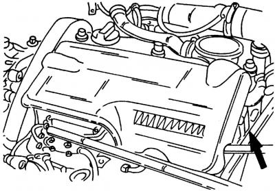
Pic. 359. Place of connection of the left hose of forced air to the radiator of charged air (shown by arrow)
- disconnect the left hose (pic. 359). Remove the charge air line from the holder on the gearbox;
- disconnect the wires from the starter: disconnect the plug (terminal «50»), unplug the cable (terminal «30») and remove the cable tie;
- lower the car to the ground;
- Drain the coolant from the cooling system as described for the gasoline engine. It is best to disconnect the lower hose for this;
- remove headlights;
- remove the upper part of the air filter;
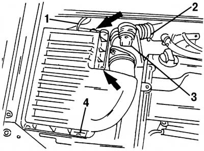
Pic. 360. Removing the upper part of the air filter: 1 - hose; 2 - inlet pipeline; 3 - plug block of the mass air flow sensor; 4 - latch
- disconnect hose 1 (pic. 360), to the EGR vacuum regulator and disconnect intake pipe 2;
- Disconnect plug 3 of the mass air flow sensor;
- disconnect three clamps 4;
Pic. 361. Place of connection of the upper hose of forced air (shown by arrow)
- remove the bottom of the air filter. To do this, first press the holder out of the outer side partition. Disconnect the top air hose (pic. 361), after loosening the hose clamp.
Pic. 362. Removing the engine cover. Cover fastening is shown by an arrow
- remove the engine cover (pic. 362);
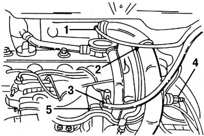
Pic. 363. Location of hoses: 1 - to the boost pressure regulator in the control device; 2 - forced air; 3 - coolant (to expansion tank); 4 - plug block of the intake air temperature sensor; 5 - upper coolant hose
- disconnect the ones shown in fig. 363 hoses and plug;
- disconnect the vacuum hoses from the turbocharger inlet pipe and from the exhaust gas recirculation valve (EGR valve);
- disconnect the fuel lines and vacuum line from the vacuum pump;
- disconnect the electrical cable from the generator and unplug the high pressure fuel pump (injection pump);
Pic. 364. Disconnect plug-in blocks: 1, 2 - crankshaft position sensor; 3 - engine wiring harness
- unplug connectors 1 and 2 (pic. 364) crankshaft position sensor, engine wiring harness connector 3. To do this, remove the appropriate spring clips to release the entire cable;
- Disconnect the reversing light switch connector;
- disconnect «mass» transmission cable. Disconnect the clutch pipe by removing the spring clip and releasing the clutch. Seal the open ends of the pipelines;
Attention! When performing the operation, pay attention to the flowing brake fluid.
- disconnect the coolant hoses going to the expansion tank and heater;
- if the machine is equipped with air conditioning, then disconnect the plug-in block of the electromagnetic clutch;
- loosen the V-ribbed belt as described below;
- loosen the wheel bolts. Place the front of the car on stands and remove the front wheels;
- remove the front suspension of the right wheel;
Pic. 365. Front wheel suspension. Tie rod 1 connects the anti-roll bar to the shock absorber
- disconnect rod 1 (pic. 365) anti-roll bar;
- Disconnect the brake hose and remove the ABS sensor cable (shows wheel speed) from the holder on the shock absorber;
- unscrew the nut of the tie rod bolt on the rudder bipod and remove the hinge using a puller from the rudder bipod;
- unscrew the two bolts at the bottom of the wheel suspension and press the ball joint of the suspension from the wheel bearing housing (rounded fist);
- carry out the described operations on the left side of the car;
Pic. 366. Removing the steering. Tie the tie rods left and right with wire loops so they don't fall off
- tie the tie rods with wire as shown in fig. 366 to both shock absorbers. Now unscrew the steering from the transverse beam, and the rods will remain hanging on the wire;
- unscrew the balancing suspension from the side of the gearbox;
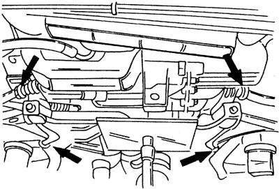
Pic. 367. The transverse beam of the front suspension is mounted in the places shown by the arrows
- place a jack with a suitable support under the cross beam, raise the jack so that it raises the cross beam, and unscrew it in the places shown in fig. 367;
- drain the gear oil. Clean the plug and then screw it back in immediately;
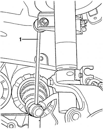
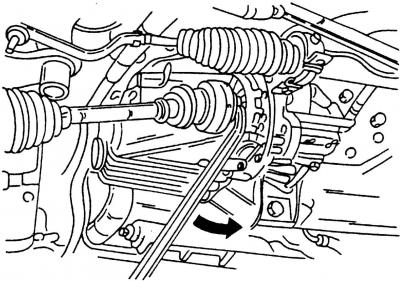
Pic. 368. Turn away the basic bearing 1 of the right power shaft and squeeze out a shaft from a transmission in the shown place 2
- remove the right wheel drive shaft from the gearbox. First unscrew thrust bearing 1 (pic. 368), and then pull the shaft at location 2 out of the spline connection with the gearbox.
Attention! When performing the operation, the car must be installed on supports.
Pic. 369. Removing the left wheel drive shaft
Remove the left wheel drive shaft using the inserted pry bar (pic. 369).
Disconnect the shift cables from the gearbox. The ends of the cables are secured with clamps. After removing the clips, pull both cables upwards from their holders.
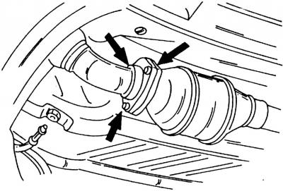
Pic. 370. The downpipe is attached to the catalyst in the places indicated by the arrows
Loosen three bolts (pic. 370) and separate the downpipe from the catalytic converter flange.
Disconnect the exhaust pipe from the turbocharger (4 bolts).
Disconnect the hose from the heating pipeline (hose connection).
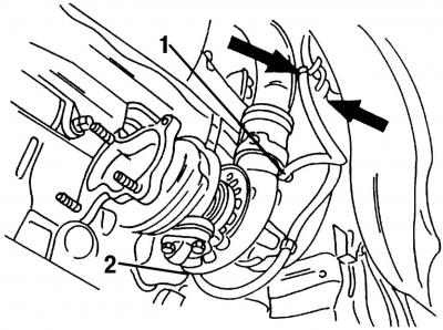
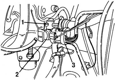
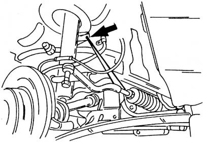
Pic. 371. Disconnect the hoses 1 from the turbocharger and 2 - from the vacuum box and release them from the mounts
Disconnect hoses from turbocharger 1 (pic. 371) and vacuum box 2 and release them from the hose fittings.
Loosen the power steering pump pipe holder (located near the pulley on the crankshaft). Loosen the power steering pump drive pulley. To hold the pulley in a stationary position, insert a suitable Allen wrench into the inside of the pump shaft.
Loosen the power steering pump bolts (one of the bolts is located in its lower part), remove the pump, take it aside and tie it with a wire.
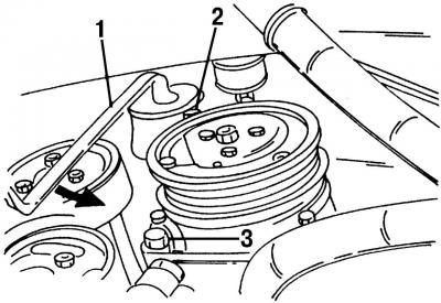
Pic. 372. Removing the air conditioning compressor
If the car has air conditioning, remove the compressor. First turn with wrench 1 (pic. 372) drive belt tensioner in the direction of the arrow so that the drive belt is loosened. Then unscrew bolts 2 and 3 and remove the compressor in such a way that no piping is damaged.
Attention! Do not disconnect pipes.
Place a jack under the power unit.
Attention! Make sure that the power unit is well fixed.
Remove the four rear engine mount bolts.
Attention! Check again that the motor is securely fastened.
Note. In a car service, a special device is used to raise the engine, under which a car lift is then substituted. On fig. 21 has already shown how the engine is supported from below, i.e. the engine should be securely supported with a jack so that it remains in its original position after unscrewing the engine mounts. To ensure this, you need to have a manual crane at your disposal. Position the crane arm above the engine compartment and secure the engine with sling eyes on the crane hook. If the jack accidentally slips, the boom will hold the engine in its original position.
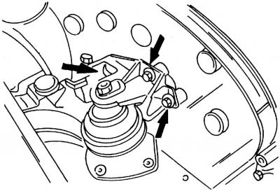
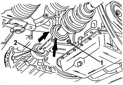
Pic. 373. Fastening of the front support (shown by arrows)
Loosen the front engine mounts (pic. 373).
Slowly lower the engine down. To do this, you will need an assistant to lower the car jack or crane while you continuously monitor the process of lowering the engine through the engine compartment. If the engine catches on something, it should be released immediately to avoid damage to body parts or other components and assemblies. This applies primarily to removed and tied parts. In addition, if possible, you can raise the front of the car to have more room to remove the engine.
Engine installation is carried out in the reverse order of the removal process, however, you should pay attention to the following points:
- check the clutch release bearing in the clutch slave cylinder for wear. If necessary, replace the slave cylinder together with the clutch release bearing. On the cars covered in the book, they should always be changed together;
- Apply some lubricant to the clutch shaft spline. Volkswagen recommends using grease with the designation G 000 100 in this area;
- Install the engine and transmission in the correct position in the engine compartment. When lifting the power unit, make sure that it does not touch the drive shafts and be sure that the engine, along with the gearbox, is well secured on a jack or lift. As already mentioned, it is most convenient to use a crane with a manual drive and an arrow;
- after the engine is level with the engine mount mounts, tighten the mount bolts (about 5-6 turns). Rock the engine a little from side to side (it should not yet be finally attracted) and tighten the front and rear engine mount bolts. Tighten the fastening of the front suspension beam, as well as the rear suspension bracket, to a torque of 55 Nm (front to hydraulic bearing).
Install the wheel drive shafts and tighten the bolts to the correct torque.
Tighten the power steering pump mounting bolts to 25 Nm. Don't forget the bolt at the bottom of the pump mount. Install the pump pulley by immobilizing the power steering pump shaft with a hex wrench, and tighten the three bolts to 23 Nm. Tighten the bracket fixing the power steering pump pipe (20 Nm).
Use new gaskets when installing the exhaust pipe on the turbocharger and at the junction of the exhaust pipe and catalytic converter.
Insert the right wheel drive shaft into the gearbox and tighten the thrust bearing (27 Nm).
Before installing the left wheel drive shaft, replace the thrust ring located at the end of the shaft.
Reposition the crossbeam in the correct position and tighten the screws shown in fig. 367 four bolts with a torque of 110 Nm.
Establish a balancing suspension bracket on a transmission. Tighten the bolt on the outside to 95 Nm.
Remove the steering from the wire and screw from below to the cross beam. The bolts are tightened with a torque of 50 Nm.
Install wheel suspension (pic. 365). Tighten both ball joint bolts to 55 Nm, tie rod joint nut to 30 Nm, connecting rod fastening nut to 100 Nm. Carry out the described operations on both sides of the vehicle.
Lower the vehicle to the ground and tighten the wheel bolts (140 Nm).
Put on the V-ribbed belt, release the tension roller so that it tensions the belt.
Connect the pipeline to the clutch slave cylinder and fix it with a spring clip. Bleed the air from the clutch system.
Install the air cleaner parts in reverse order of removal.
Visitor comments