



Contents: Checking valve springs ↓ Valve guide bushings ↓ Valve seats ↓ Valves ↓ Cylinder head ↓ Camshaft ↓
Checking valve springs
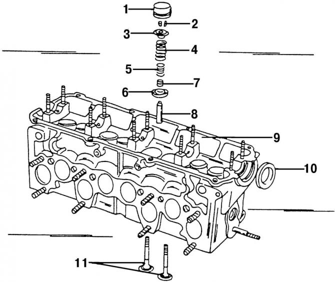
Fig. 396. Valve details: 1 - plate pusher; 2 - halves of the valve conical chamfer; 3 - upper valve spring plate; 4 - outer valve spring; 5 - inner valve spring; 6 - lower valve spring seat; 7 - oil deflector cap; 8 - valve guide bushing; 9 - cylinder head; 10 - camshaft oil seal; 11 - valves
Checking the valve springs is done in the same way as for a petrol engine (the valve details are shown in Fig. 396).
Valve guide bushings
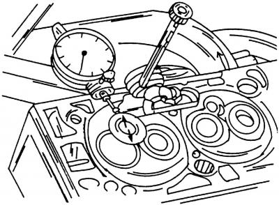
Fig. 397. Checking the valve stem clearance in the valve guide bushing with an indicator
(The text is copied from this portal: «VWMANUAL.ru»)
Install the indicator as shown in Fig. 397 and insert the valve. Rock the valve plate from side to side at the top and check the indicator reading. If the reading is more than 1.3 mm, replace the valve guide. Since the difference in size between the inlet and outlet valves is very small, be very careful not to confuse the inlet and outlet valves and insert them only into the appropriate holes.
The cylinder head can be used after grinding if it has small scratches between the valve seats, provided that the scratches are not wider than 0.5 mm.
To replace the valve guide, press out the old guide using a suitable drift from the camshaft side of the cylinder head. If you notice that the valve guides are fastened, they should be pressed out from the combustion chamber side (the replaced bushings have a screwed fastening). The cylinder head can be heated to facilitate this operation. Screw a pin that fits the inside of the valve guide sleeve onto the punch that is intended for pressing out the valve guide sleeve.
If it is necessary to replace the valve guide bushing, replace the valve itself along with it. After that, grind the valve seats.
Lubricate the new valve guides well with oil and press them into the cold cylinder head from the camshaft side so that the flange of the valve guide fits into the cylinder head. The pressing pressure should not be more than 1 t, otherwise the flange may be cut off.
After pressing in, process the valve guide bushing with a special reamer. Process the guide bushings of the intake and exhaust valves with an 8.0 mm reamer. This will automatically produce the correct clearance of the valve guide bushings.
Caution! If the valve guides have been replaced, the valve seats must be milled.
Valve seats
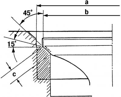
Fig. 398. Valve seat view (The values of the measurements shown are given in the adjustment and control table.): a - valve seat diameter; b - valve head diameter; c - valve seat width
Machine the valve seats according to the dimensions shown in Fig. 398. Check all valve seats for wear and scratches. Light wear can be removed with a milling cutter (45°). If the seat is heavily worn, mill the valve seats again. As already stated, if the valve bushings have been replaced, the valve seats must be lapped.
Take the following measurements to determine the additional machining size for the valve seat:
- insert the valve into its guide bushing and press down on the valve seat;
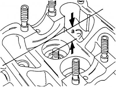
Fig. 399. Measuring depth a during additional processing of valve seats (shown by arrows)
- measure the interval a (Fig. 399) between the top of the valve and the top edge of the cylinder head;
- calculate the maximum and minimum permissible value of the measured value after milling. On the inlet valves it should be 35.8 mm, on the outlet valves - 36.1 mm. If you subtract the minimum distance from the measured value, you will get the maximum permissible value. This will be important when performing the work described below.
The valve seats should be milled if new guide bushings have been installed. To do this, you need to:
- machine the upper edge of the valve seat with a milling cutter at an angle of 45°, and then with a milling cutter at an angle of 15° (Fig. 398) to reduce the width of the valve seat and bring it to 2.7 mm for intake valves and 2.05 mm for exhaust valves. The machining should be stopped as soon as the valve seat dimensions reach the specified dimensions. The exhaust valve seats have diameter limiters. When machining, be careful not to damage these limiters;
- to avoid boring the valve seats in the cylinder head too much, be sure to take the measurements described above;
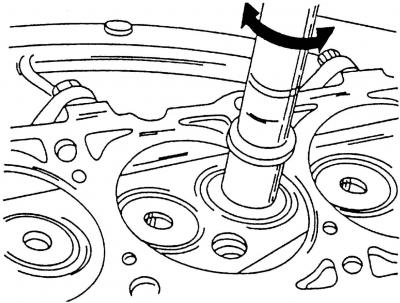
Fig. 400. Valve grinding
- grind the machined valve seats. To do this, apply a small amount of lapping paste to the valve seat and install the valve in the corresponding seat. Grind it with a back and forth rotational motion (Fig. 400);
- after lapping, thoroughly clean all parts from dirt and lapping paste and check the valve seat in the area of the valve plate and sealing ring. A continuous matte ring should be visible on both parts;
- draw a few lines on the ring in the valve plate with a pencil. The lines should be drawn around the ring at intervals of approximately 1 mm. After this, carefully insert the valve into the guide sleeve, lower it onto the seat and turn it around 90°, applying a slight force to the valve;
- remove the valve and check if the pencil lines on the sealing ring have disappeared.
If the valve seat width matches the specified dimensions, the cylinder head can be installed. Otherwise, the valve seats must be re-machined or, as a last resort, a new cylinder head must be installed.
Valves
Minor damage to the valve head surface can be repaired by grinding the valves into the cylinder head seats as described above.
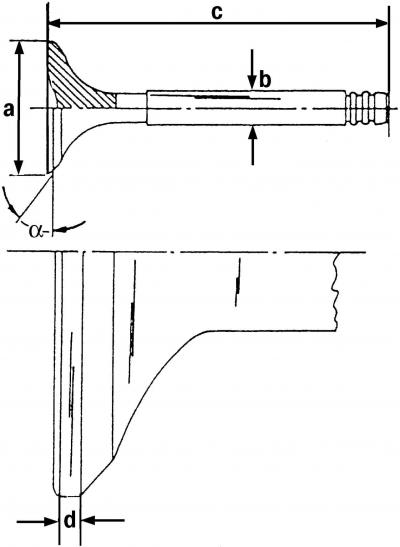
Fig. 401. Main dimensions of valves. The exact values of the quantities should be looked up in the adjustment and control table. The value of d cannot be less than the minimum nominal value of this dimension: a - valve plate diameter; b - valve stem diameter, c - valve length; d - edge of valve plate; a = 45°
Take measurements (Fig. 401) and replace all valves that do not correspond to these dimensions. The values corresponding to the designations a, b and c can be taken from the tolerance and control table.
If the ends of the valve stems are worn, they can be ground on a grinding machine, provided that no more than 0.5 mm of material is removed during grinding.
The inlet valve plates can be ground on a valve grinding machine, provided that the value b (Fig. 401) is not less than 0.5 mm.
Machine grinding is not allowed for exhaust valves, as they are made of a special material. Only grinding with paste can bring the exhaust and intake valves back to normal or, otherwise, replace them.
Cylinder head
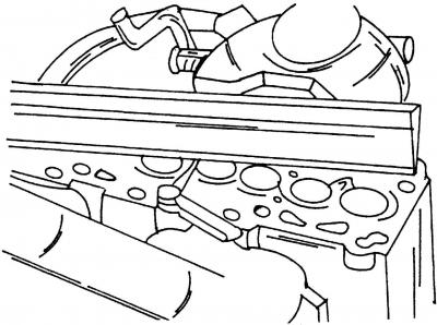
Fig. 402. Checking the cylinder head for deformation using a measuring ruler and feeler gauge
Carefully clean the mating surfaces of the cylinder head and cylinder block and check the cylinder head surface for deformation. To do this, place a measuring ruler (Fig. 402) on the head and use a measuring probe to check the clearance lengthwise, crosswise and diagonally. If the probe can be inserted more than 0.1 mm, the cylinder head must be ground. If the gap is larger in any place, the cylinder head must be replaced, since removing a larger layer of metal is unacceptable. Deformation of the cylinder head surface can occur, for example, when the engine overheats.
Camshaft
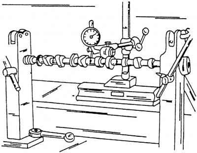
Fig. 403. Checking the camshaft runout
To determine the wear of the camshaft, clamp it as shown in Fig. 403 and install the indicator on the journal of the central bearing. If the device shows a deviation of more than 0.01 mm, then the camshaft is deformed and must be replaced.
Check the camshaft journals for damage.
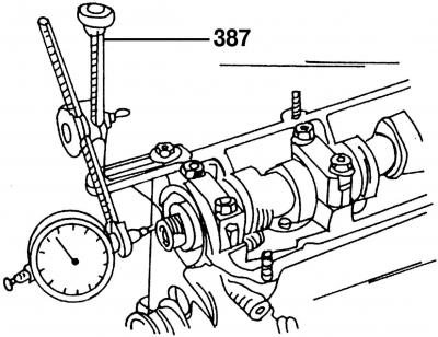
Fig. 404. Measuring the axial clearance of the camshaft
To measure the camshaft end clearance, place the camshaft into the cylinder head (without pushers) and secure it with the outer bearing caps. Install the cylinder head on a smooth surface. Install the indicator on the end surface (Fig. 404) and move the shaft back and forth in the direction of the axis. The gap should not be more than 0.15 mm. Otherwise, the bearing cap support surface is worn out.
Visitor comments