
If pistons, parts of the crank mechanism or cylinder block have been replaced, then the distance that the pistons protrude above the cylinder head must be re-measured.
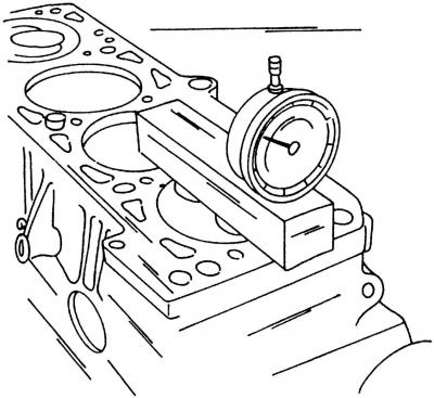
Pic. 409. Measuring the distance over which the pistons protrude to determine the thickness of the cylinder head gasket
In order to determine the thickness of the cylinder head gasket, you need to put one of the pistons in the TDC position and, using a ruler and an indicator, determine how far the piston bottom protrudes above the surface of the cylinder block (pic. 409). By measuring this distance and using the data below, determine the thickness of the cylinder head gasket.
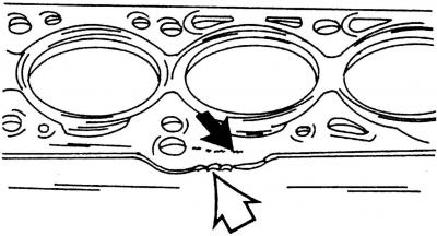
Pic. 408. View of the cylinder head gasket
Cylinder head gasket marked with 1, 2 or 3 or marked with holes (pic. 408). The arrow shows the part number on the cylinder head gasket. If the cylinder head gasket is installed correctly, this number can be read by looking at the cylinder head gasket from above.
| Piston protrusion | Number of notches |
| 0.91-1.00 mm | 1 |
| 1.01-1.10 mm | 2 |
| 1.11-1.20 mm | 3 |
As already mentioned, the cylinder head gasket can be marked with punched holes. In this case, you should read «number of notches», A «number of holes».
To measure, install the indicator pin on the piston, set the meter to zero, and then slide the pin onto a thoroughly cleaned surface of the unit. The resulting value is equal to the distance the piston protrudes from the cylinder head. The depth is difficult to measure, as it is very small. The gasket number should be determined from the spare parts catalog.
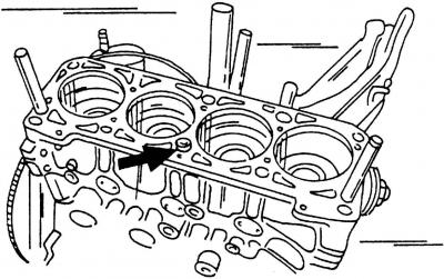
Pic. 410. In the places shown on the cylinder block, two special screws must be screwed (or two pins). guide sleeve (shown by arrow) must be pressed into the side of the cylinders
Special guide bolts are available to center the cylinder head when installed on the cylinder block. If you purchase them, then install in the one indicated in fig. 410th place, i.e. on «cold» side of the engine. Otherwise, set screws must be made to be screwed into the indicated locations in order to properly align the gasket and cylinder head. The figure also shows the guide sleeve that must be located in the unit.
Thoroughly clean the surfaces of the cylinder head and assemblies.
The gasket should be removed from the packaging just before installation and handled with great care. Place the gasket on the cylinder head and slide the cylinder head onto the cylinder block.
Slide the cylinder head onto both guide screws (pic. 410), install the guide bushing and tap it with a plastic or rubber mallet.
Insert the cylinder head bolts and tighten by hand.
Remove both guide screws from the cylinder block.
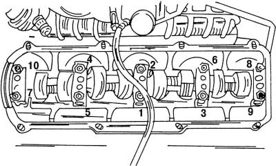
Pic. 411. The order of tightening the bolts of the cylinder head
Guided by Fig. 411, gradually tighten the cylinder head bolts in the sequence shown and in accordance with the following recommendations:
Attention! To tighten the cylinder head bolts, use only a special 12-point wrench, otherwise the bolt heads will be damaged.
- tighten all bolts (pic. 411) in the specified sequence with a torque of 40 Nm;
- tighten all bolts (pic. 411) in the specified order with a torque of 60 Nm;
- in the order shown, insert the wrench into each bolt, remembering the position of the wrench, and tighten each bolt in one go exactly a quarter of a turn, without using a torque wrench. After you've done this on all the bolts, tighten them another quarter turn.
Note. If you are familiar with earlier diesel engines, you probably know that the cylinder head bolts used to be tightened with the engine warmed up to its operating temperature. This is no longer the case - the cylinder head is tightened in accordance with the instructions given.
All further installation work is carried out in the reverse order of the removal process (17.3.1).
Visitor comments