
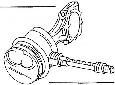
Pic. 429. Removal and installation of the piston pin using a special mandrel
Insert the piston pin into the heated piston and connecting rod by hand. On fig. 429 shows how the piston should be positioned when installing the piston pin.
When assembling the piston and connecting rod, the following recommendations should be observed:
- If you are reusing old pistons, then make sure that the markings you applied are correct. When installing new pistons, pay attention to the marking in the form of numbers on the pistons, i.e. 1/2 or 3/4;
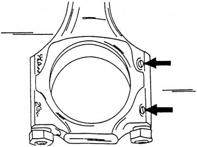
Pic. 423. The arrows show cast protrusions. The bearing shell tongues are located on the same side
- cast lugs on connecting rod and bearing cap (pic. 423) must point towards the intermediate shaft and engine pulleys;
- the mark in the form of the cylinder number must match on the connecting rod and the bearing cap;
- insert retaining rings on both sides of the piston and make sure they are firmly seated in the grooves;
- check if the piston on the connecting rod moves back and forth freely.
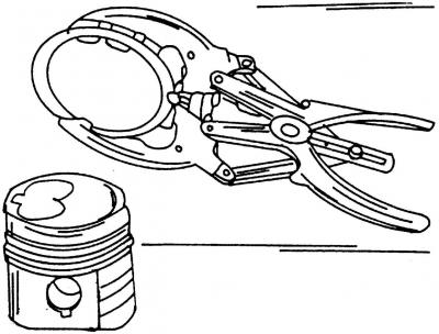
Pic. 425. Removal or installation of piston rings
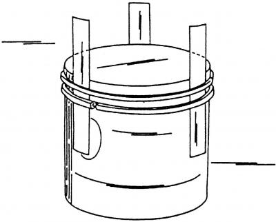
Pic. 426. Schematic representation of the removal or installation of piston rings
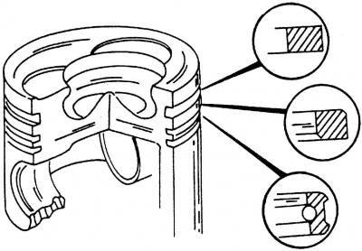
Pic. 430. The cut and location of the piston rings when they are installed on the piston
With piston ring pliers (pic. 425), install the piston rings one by one into the grooves. If you don't have a piston ring installer, use metal strips (pic. 426). To do this, install the rings at the level of the grooves on the piston and, having pulled out the metal strips, install the piston rings in their grooves. Check the cross section of the rings before installing them (pic. 430). Both compression piston rings are marked on one side with the words «Oben» or «Thor» and this marking must be visible after installing the ring on the side of the piston crown.
Prior to installation, lay the assembled pistons on a clean surface and cover to prevent dust from entering them.
Visitor comments