



Lubricate the cylinder bores generously.
Lay out all connecting rods according to cylinder numbers. The cast projections on the connecting rod and connecting rod cap should be directed towards the intermediate shaft.
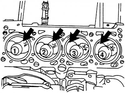
Fig. 422. View of the upper part of the engine. The arrows indicate the large recesses for the inlet valves, which are located differently on pistons No.1 and 2, No.3 and 4
Lay out all the pistons in the order in which they are installed (Fig. 422).
Distribute the piston ring joints over the cylinder surface so that they are located relative to each other at an angle of 120°.
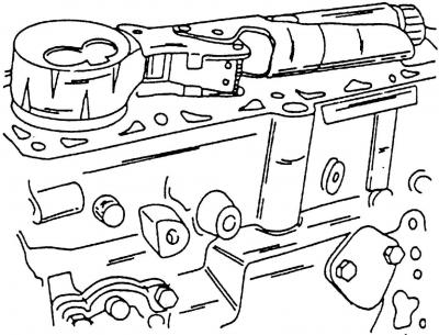
Fig. 431. Using a tension band clamp when installing pistons
Place the mandrel for installing the piston with rings in the cylinder on the piston ring area (Fig. 431) and press the piston rings into the piston grooves. Check that the piston rings are fully seated in their grooves. If you do not have a special mandrel, you can use a thin metal strip, wrap it around the piston rings and squeeze it so that the rings enter the grooves on the piston.
Turn the crankshaft so that the two crankpins of the crankshaft are at BDC.
Insert the connecting rod from above into the cylinder bore. To do this, lay the engine on its side so that the connecting rod can be directed at the main journal, and at the same time the surface of the cylinder and the connecting rod journal are not scratched. The connecting rod bearing shell should already be in the connecting rod with the protrusion in the recess.
Insert the pistons so that the rings enter the cylinder holes one by one and the connecting rod heel sits on the connecting rod journal of the crankshaft.
Insert the second bearing shell into the bearing cap so that the bearing shell fits into the groove of the bearing cap, and lubricate the surfaces of the shells well. Press the connecting rod cap onto the connecting rod and tap it lightly.
Caution: Make sure both cast tabs are positioned together.
Lubricate the connecting rod bolts and connecting rod threads with oil.
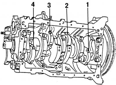
Fig. 432. Tighten the bolts shown to 30 Nm + 90°
Tightening of connecting rod bearing bolts occurs according to a certain pattern. As already mentioned, always replace the bolts with new ones. Alternately tighten the connecting rod bearing bolts (Fig. 432) with a torque of 30 N·m and then turn them from the final position by another 90° (a quarter turn), without using a torque wrench.
Caution: When measuring the axial clearance of the connecting rod bearings, use the old connecting rod bearing bolts, since if new bolts are used for this purpose, they cannot be tightened a second time.
After installing the connecting rod, turn the crankshaft several times to immediately make sure that it rotates easily, without jamming.
Check the markings on all connecting rods again and make sure the pistons are pointing in the correct direction. Also make sure the recesses for the oil jets are on the correct side.
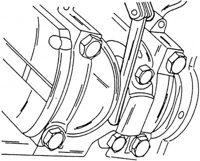
Fig. 433. Measuring the clearance between the side planes of the connecting rod and the surface of the crankshaft
Using a feeler gauge, measure the gap between the side surfaces of the connecting rod and the surface of the crankshaft (Fig. 433) - the axial clearance of the connecting rod bearings should not exceed 0.37 mm.
Visitor comments