



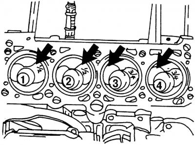
Fig. 422. View of the upper part of the engine. The arrows indicate the large recesses for the inlet valves, which are located differently on pistons No.1 and 2, No.3 and 4
Mark each piston and its connecting rod with the cylinder number from which they were removed. This is best done by marking the cylinder number in color on the bottom of the piston. Draw an arrow on the bottom of the piston pointing to the front of the engine. Since the piston can be installed the other way around, i.e. turned 180°, follow Fig. 422.
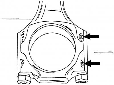
Fig. 423. The arrows indicate the cast projections. The bearing shell tongues are located on the same side
When removing the piston with the connecting rod, observe the exact direction of installation of the connecting rod cap and immediately after removal apply the cylinder number to the connecting rod and connecting rod cap on the side. It is best to do this with a center punch (for example, for cylinder No.1 - one blow with a center punch, etc.). The connecting rods and connecting rod caps must be combined in such a way that both cast projections are located opposite each other (Fig. 423). Both projections after installing the connecting rods must always be located on the side of the intermediate shaft, and point to the side of the engine where the drive belt is located.
On one side, the pistons have a cutout for the oil cooling nozzles to prevent the nozzles and pistons from colliding at the bottom dead center. The pistons should be installed with this side facing the nozzles.
After removing the connecting rod bearing caps, replace the connecting rod bolts.
Mark the bearing shells according to the connecting rod and connecting rod cap. Also mark the upper and lower bearing shells on their back side with a marker.
Remove the connecting rod bearing caps and liners.
Tap the pistons and connecting rods outwards with the handle of a plastic hammer from the inside of the cylinder block. If necessary, scrape off any oil deposits on the top of the cylinder with a scraper, but be careful not to damage the cylinder surface.
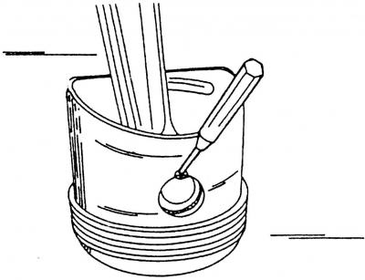
Fig. 424. Removing the retaining ring from the piston pin hole. A sharp mandrel is used for this purpose
Remove the safety clamps and press out the piston pins. The recess in the piston pin hole facilitates the use of a tool, so you can easily remove the safety clamps (Fig. 424). Press out the pin with a suitable drift.
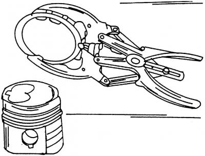
Fig. 425. Removing or installing piston rings
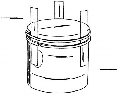
Fig. 426. Schematic representation of removal or installation of piston rings
Remove the piston rings one by one through the piston crown using a piston ring puller (Fig. 425). If you plan to reinstall the rings, they should be marked accordingly. If you do not have a piston ring puller, you can insert metal strips opposite each other under the rings. Be sure to place one of the strips under the ring lock to avoid scratches (Fig. 426).
Visitor comments