



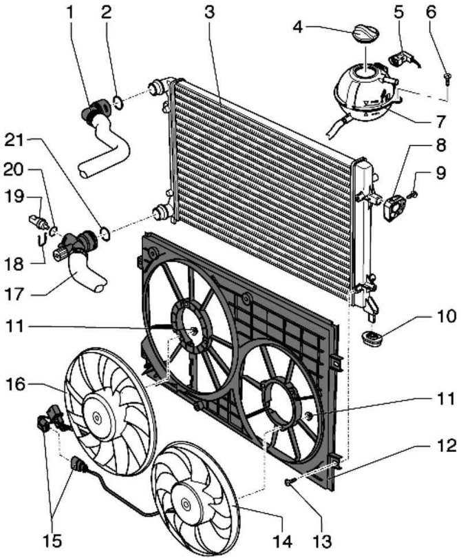
Fig. 2.61. Cooling system elements installed on the body: 1 – coolant hose, upper; 2 – O-ring round section; 3 – radiator; 4 – lid; 5 – plug; 6 – bolt 5 Nm; 7 – expansion tank; 8 – bracket; 9 – bolt 5 Nm; 10 – support; 11 – bolt 10 Nm; 12 – Fan bracket; 13 – bolt 5 Nm; 14 – radiator fan; 15 – plug; 16 – radiator fan; 17 – coolant hose, lower; 18 – mounting bracket; 19 – coolant temperature sensor at the radiator outlet; 20 – O-ring round section; 21 – O-ring round section
Caution: When performing all installation work, particularly in the engine compartment, due to the tight layout, please note the following:
Attention: Lines of all types (for example fuel, hydraulic, activated carbon canister, cooling systems, refrigerant, brake lines, vacuum hoses), and also the electrical wires must be laid as they were originally laid.
Caution: Ensure sufficient clearance to all moving and hot components to avoid any damage to lines.
Note: When the engine is warm, the cooling system is under pressure. If necessary, release the pressure before repair work.
Note: The hose connections are secured with spring clamps. When repairing, use only spring clamps.
Note: It is recommended to use spring clamp pliers to install spring clamps.
Note: When installing, route the cooling system hoses without pulling them. Make sure that they do not touch other components (observe the markings on the radiator pipe and hose).
Visitor comments