
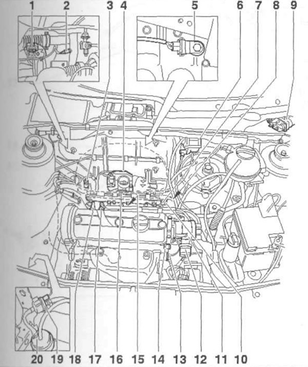
Pic. 3.28 a. Location of elements of the fuel injection system:
1 - 4-pin wiring connector; 2 - Oxygen sensor; 3 - Intake manifold pressure sensor with inlet air temperature sensor; 4 - Throttle valve block; 5 - Knock sensor 1; 6 - Ignition coil; 7 - Fuel line; 8, 13 - Connection on «mass»; 9 - Engine control unit; 10 - Fuel pressure regulator; 11 - Ignition distributor; 12 - Central connector; 14 - Coolant temperature sensor; 15 - Nozzle; 16 - Air filter; 17 - Spark plug; 18 - Oil pressure sensor; 19 - Solenoid valve 1 activated carbon filter; 20 - Activated carbon filter.
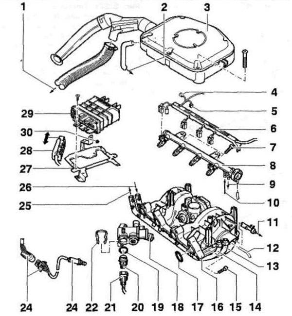
Pic. 3.28 b. Location of elements of the fuel injection system:
1 - To the connecting pipe for heating the incoming air on the exhaust manifold; 2 - To the oil separator; 3 - Air filter; 4 - 4-pin wiring connector for intake manifold pressure sensor with intake air temperature sensor; 5 - 8-pin wiring connector for throttle body; 6 - Electrical wiring guide; 7, 15, 30 - Bolts; 8 - High pressure fuel line with nozzles; 9 - To the drain fuel line; 10 - Adapter for injection fuel line; 11 - To the servo steering; 12 - Vacuum tube; 13 - Delivery fuel line; 14 - Drain fuel line; 16 - Intake manifold; 17, 19 - O-rings; 18 - Thermostat housing; 20 - Coolant temperature sensor; 21, 28 - Wiring connectors; 22 - Retainer; 23 - Oxygen sensor; 25 - 4-pin wiring connector for oxygen sensor; 26 - To the fuel tank; 27 - Mounting plate; 29 - Engine control unit.
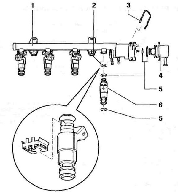
Pic. 3.28 in. High pressure fuel line with injectors:
1 - High pressure fuel line, 2, 3 - Clamps; 4 - Fuel pressure regulator; 5 - O-ring; 6 - Nozzle.

Pic. 3.28 Intake manifold:
1 - Intake manifold pressure sensor with inlet air temperature sensor; 2, 5 - O-rings; 3 - Intake manifold; 4 - Throttle body; 6 - Bolt; 7 - Connection on «mass»; 8 - Delivery fuel line; 9 - Drain fuel line; 10 - To the solenoid valve 1 of the activated carbon filter; 11 - Retainer.
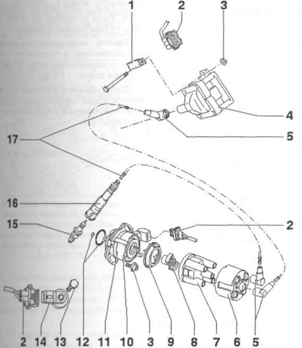
Pic. 3.28 d. Location of elements of the ignition system:
1 - Connection on «mass»; 2 - Wiring connector; 3 - Nut; 4 - Ignition coil; 5 - Jammer (0.6-1.4 kOhm); 6 - Screening cover; 7 - Ignition distributor cover; 8 - Rotor (slider); 10 - Cylinder mark No. 1; 11 - Ignition distributor with Hall sensor; 12- O-ring; 13 - Bolt; 14 - Knock sensor 1; 15 - Spark plug; 16 - The tip of the spark plug; 17 - High voltage wires.
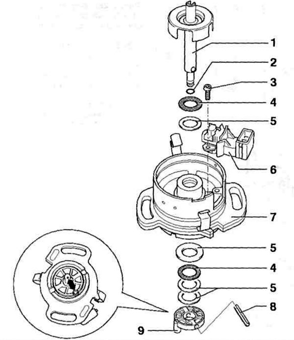
Pic. 3.28 e. Arrangement of elements of the distributor of ignition:
1 - Distributor shaft with Hall sensor rotor; 2 - O-ring; 3 - Bolt; 4 - Plastic washer; 5 - Adjusting shims; 6 - Hall sensor; 7 - Distributor body; 8 - Cotter pin; 9 - Coupling.
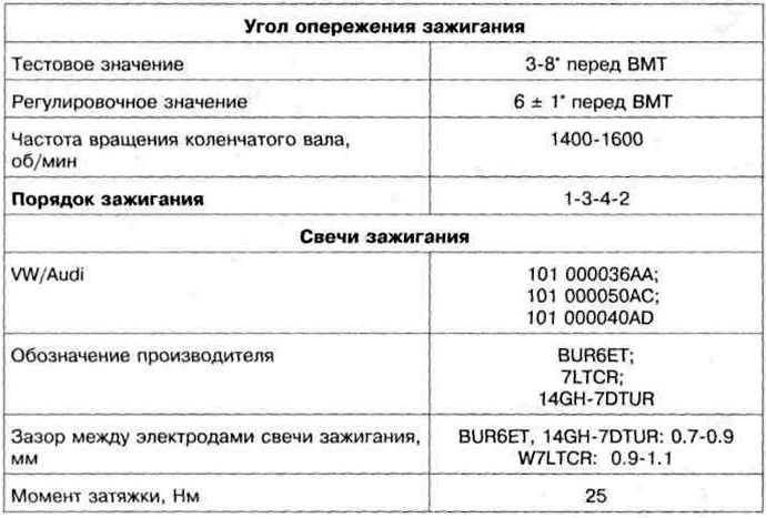
Table 3.2. Adjustment data of the ignition system and marking of spark plugs
Visitor comments