
b) Start the engine and install the throttle adjusting screw on the third tooth of the choke speed cam 1 (pic. 3.16)
 Pic. 3.16. Suction idle speed adjusting bolt
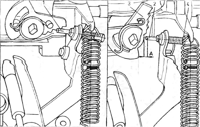
1 - adjusting bolt; 2 - cam; 3 - gap between the cam and the bolt.
V) Write down the value of the rotation speed from the speed meter.
G) If the rotation speed exceeds the limits specified in the technical data, remove the safety plug and adjust by screwing and unscrewing the bolt 1.
d) After adjusting the speed to the normal value, check if there is a gap of 0.2 mm between the edge of the adjusting screw 2 and the choke speed cam 3 when the diaphragm is fully open (pic. 3.16).
e) On the right side, install a new safety plug 4 and disconnect the speed meter
14. The flow rate of the accelerator pump can be checked both on the carburetor installed on the engine and on the removed one. However, the air filter must be removed and the float chamber filled with fuel. Open the diaphragm of the starting equipment and hold it in this position with a piece of wire, then press a piece of suitable plastic tube onto the pump nozzle, motor and throttle. Hold until fuel appears in the tube. Then place the tube in the measuring cylinder with a scale of 0.2 cm3.
Perform five full throttle strokes (for at least two seconds) for one throttle stroke. Divide the amount of fuel collected in the cylinder by 5 to determine the amount per stroke and compare the result with the value indicated in the technical data. In case of very low pump performance, change the position of the adjusting screw on the accelerator pump lever (on the right in Fig. 3.17) or turn nut 1 (on the left in the same figure), to increase lever travel.
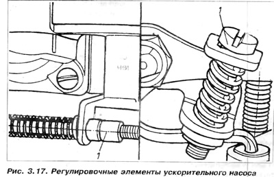
Attention: Pay attention to that. that fuel should be injected into the throttle gap. If necessary, bend the nozzle tube. Very low performance of the accelerator pump can cause engine malfunction during a sharp throttle opening.
15. Throttle gap adjustment is as follows:
A) Remove carburetor.
b) Turn the carburetor, close the diaphragm and throttle.
V) Using drill 2 (fig 3.18) appropriate diameter, check the gap between the throttle plate and the throat wall.
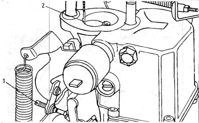
Pic. 3.18. Throttle gap adjustment
1 - adjusting screw; 2 - drill.
G) If the gap size does not correspond to that specified in the technical data, remove the safety plug and adjust the throttle position by turning the adjusting screw 1 (pic. 3.18).
d) After completing the adjustment, install a new safety plug and install the carburetor as described earlier.
e) After installing the carburetor on the engine, it is necessary to check the idle speed and the composition of the mixture.
16. Idle speed adjustment - 31 PIC-7. Precise adjustment of the carburetor is possible only after the ignition, the closing angle of the breaker and the gaps between the electrodes of the spark plugs are adjusted. Incorrect valve clearances can also affect carburetor adjustment. It must be remembered that safety plugs can be put on the engine idle adjusting screws.
A) Start the engine and warm it up to normal operating temperature, then shut it down. Connect a speed meter and an exhaust gas localizer to the engine.
b) It must be remembered that the idle speed adjustment is carried out with the radiator fan running.
V) Disconnect the main crankcase ventilation hose from the air filter and plug the filter inlet.
G) Start the engine and leave it at idle. Check whether the engine speed and the CO content in the exhaust gases correspond to the data in the technical specifications. If these values are incorrect, it is necessary to turn within a certain range with two adjusting screws located above the solenoid shut-off valve (pic. 3.13).
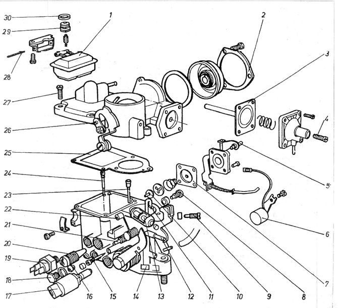
Pic. 3.13. Carburetor 31 PIC-7
1 - float; 2 - fixing ring; 3 - servomotor diaphragm; 4 - adjusting screw of the diaphragm gap; 5 - adjusting bolt flow rate of the accelerator pump; 6 - heater of the partial throttle opening channel; 7 - pump diaphragm; 8 - additional fuel jet; 9 - idle jet; 10 - fungal valve; 11 - nozzle of the accelerator pump; 12 - fitting for connection with the air filter temperature controller; 13 - adjusting bolt for diaphragm clearance; 14 - designation of the type of carburetor; 15 - adjusting bolt for the composition of the mixture, 16 - main fuel jet; 17 - side air valve; 18 - cork; 19 - thermal switch of the heater of the channel of partial opening of the throttle; 20 - idle speed adjusting bolt; 21 - fitting for connecting the reduced pressure pipe of the ignition timing regulator; 22 - roller of the lever for uniform operation of the engine; 23 - air braking jet with emulsion tube; 24 - additional air jet; 25 - gasket; 26 - eccentric kingpin; 27 - carburetor cover bolt; 28 - float axis; 29 - needle valve; 30 - adjusting washer for the needle valve.
d) If an exhaust gas analyzer is not available, the mixture ratio can be approximately adjusted by turning the mixture ratio screw 15 to obtain the highest engine speed at a given screw 20 position.
e) Connect the main crankcase vent hose.
If there is an increase in carbon monoxide in the exhaust gases, this indicates dilution of the oil with fuel and requires an oil change. Another way, if an oil change seems unreasonable, is to drive the car for extended periods of time, which should reduce the amount of fuel in the oil. The reason for the increased CO content in the exhaust gases after connecting the main crankcase ventilation pipe may be the wear of the piston-cylinder pair and the associated increased exhaust gas purge.
e) Shut off the engine and turn off the rpm meter and exhaust gas analyzer.
17. Adjusting the fuel level in the float chamber:
A) Before checking the fuel level in the float chamber, run the engine for a minute so that the fuel level reaches the normal value.
b) Stop the engine and remove the air filter assembly.
V) Remove the carburetor cover and gasket and use a depth gauge or vernier caliper to measure the distance from the top surface of the carburetor body to the surface of the fuel. This distance is specified in the technical data. The fuel level is adjusted by replacing the gaskets under the needle valve. The basic thickness of the gasket is 2.0 mm If the fuel level is very high, it is necessary to put on a thicker gasket and vice versa, if the level is very low, it is necessary to put on a thinner gasket. The fuel level rises during operation as a result of needle valve wear.
Valve wear is determined by the deepening of the needle into the seat, causing a decrease in the effective length of the valve and an increase in the fuel level. During adjustment, it is necessary to increase its length by putting on a thicker washer.
G) After replacing the washer, put the cover on the carburetor and tighten it with two bolts.
d) Connect the fuel pipes, supply and return, as well as the wire to the battery ground.
e) Run the engine for a minute to check the fuel level in the float chamber.
and) Disconnect the ground wire, remove the cap from the carburetor and check the fuel level. If the level is normal, install the carburetor cap and perform the rest of the operations in the reverse order of removal.
Attention: The amount by which it is necessary to increase the thickness of the gasket (washers) needle valves, difficult to determine. It can only be established by the method of serial probing. The value primarily depends on the difference between the measured and normal fuel levels, as defined in the technical data.
It is possible to increase the thickness of the gasket by a thickness of 0.2 mm or more. Often, due to the lack of shims, it is allowed to bend the tongue on which the valve needle rests. However, it must be borne in mind that this is not a completely correct solution, especially if the tongue is bent at a large angle and the distribution of forces acting on the needle changes. The force begins to act not along the needle, but at an angle to the socket. This can lead to (especially with worn valves) to the formation of leakage.
Visitor comments