
A) Connect a speed meter to the engine.
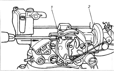
b) Open the throttle, fully close the diaphragm, then release the throttle. The suction speed adjusting screw must be located on the top tooth of the suction speed cam (pic. 3.23).
Pic. 3.23. Carburetor Zehith 2B5
1 - adjusting screw; 2 cam.
V) Without depressing the gas pedal, start the engine and record the intake speed.
G) This speed should be 3600 rpm. If it is different, it must be adjusted by removing the safety plug and turning the adjusting screw 1.
2. The position of the adjusting screws is shown in Figure 3.24.
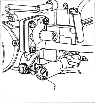
Pic. 3.24A. Carburetor - 2V5
1 - adjusting bolt for the composition of the exhaust gases.
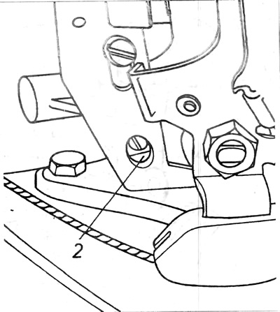
Pic. 3.24V. Carburetor - 2V5
2 - idle speed adjusting bolt.
A) Remove the waterbox cover and the bimetal spring assembly of the starting equipment. It is not necessary to disconnect the heater electrical wire and water hoses from the cover assembly.
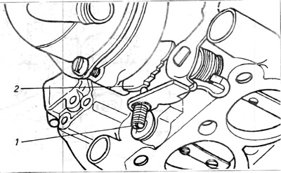
b) Rotate the throttle to set the suction speed cam so that the stop bolt is on the highest tooth of the cam. Using a screwdriver, push diaphragm rod 1 to its limiter. Use rubber band 2 to support the diaphragm control lever, pressed to its limit.
3 a) Remove the waterbox cover and bimetallic spring assembly of the starting equipment. It is not necessary to disconnect the heater electrical wire and water hoses from the cover assembly.
b) Rotate the throttle to set the rotation speed cam on the suction so. so that the limit bolt is on the highest tooth of the cam Using a screwdriver, press the diaphragm rod 1 to its limiter (pic. 3.25). Use rubber band 2 to support the diaphragm control lever pressed against its limiter
Pic. 3.25. Carburetor Zenith 2B5
1 - diaphragm rod, 2 - pressure rubber.
V) It is easy to press the diaphragm. The inclination and closing of the diaphragm eliminates any gaps on the joints of the mechanism. Then check the gap between the lower edge of the diaphragm and the neck wall with a diameter of 3.7 mm.
G) If necessary, adjust this gap by turning the adjusting screw on the end of the diaphragm rod.
d) After completing the adjustment, install the starter equipment cover. The sign on the cover must match the corresponding sign on the body of the launching equipment.
4. Thrust of the second pass of the carburetor:
The second pass throttle is controlled by rarefied air through a reduced pressure servomotor, which is connected to the throttle lever with a short link. In the 2V5 carburetor, this assembly is made of artificial material and is not adjustable.
5. Fuel level:
To check the fuel level, you must remove the top cover of the carburetor. Since this requires the start diaphragm connecting rod to be disconnected, it is recommended to check the start diaphragm clearance after installing the carburetor top cap to ensure that the cap is seated properly. Unscrew the top cover of the carburetor, as shown in fig. 3.26, it is impossible to measure the distance from the top of the float to the plane (without gasket). During the measurement, the float must not be pressed with the measuring tool. Size a is shown in Fig. 3.26.
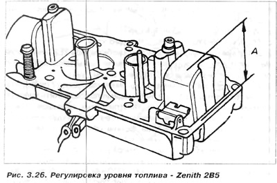
Dimension A: for the first pass - 28 mm, for the second pass - 30 mm.
This check is best done using a suitably cut template made of hardboard or similar material. If adjustment is necessary, the arms of the float can be bent. To do this, the float must be removed.
6. Thermal switch:
On the 2V5 carburetor, a thermal switch assembly similar to that found on the 1V3 carburetor controls the power supply to the auto-suction heater and drive manifold preheater assembly. It is necessary to check the thermal switches, their required values, measured during the test, as well as for the 1VZ carburetor.
Visitor comments