
1. Checking the heating element in the drive manifold. When checking the heating element, the engine must be cold.
A) Disconnect the electrical wire from the heating element 24, then turn on the thermometer between the electrical end of the element and the ground - the scale should show 0.25-0.50 (pic. 3.27).
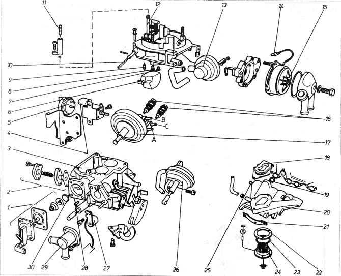
Pic. 3.27. Carburetor 2E2
1 - accelerator pump assembly; 2 - mixture enrichment valve with partial throttle opening (Once removed, the valve must be replaced with a new one); 3 - float chamber; 4 - valve that controls the disconnection of the idle system and at speeds higher than the idle speed; 5 - thermo-temporary valve; 6 - float; 7 - main jet of the first pass; 8 - main jet of the second pass; 9 - needle valve; 10 - filter; 11 - adjusting bolt of the exhaust gas composition; 12 - idle jet; 13 - servomotor; 14 - plug; 15 - automatic start equipment cover; 16 - valves for adjusting the idle speed (lower only available with four output servomotor); 17 - servomotor with three outputs; 18 - A, B, C - fittings for connecting the servomotor (four outputs have servomotors in cars with automatic transmission); 18 - shock-absorbing cuff; 19 - additional gasket type o-ring (boxing ring) between the manifold and the head, 20 - drive manifold; 21 - holder; 22 - washer; 23 - gasket; 24 - mixture heater; 25 - fitting for connecting the servo; 26 - servomotor controlling the opening of the second passage; 27 - heater of the partial throttle opening channel; 28 - adjusting bolt; 29 - valve cover with coolant fittings; 30 - mushroom valve.
b) To remove the heating element, it is necessary to disconnect the electrical wire from it, then unscrew the bolts at the bottom of the drive manifold and remove the element.
V) Remove O-ring 22 and gasket 23. They must always be replaced with new ones during assembly.
G) The heating element is controlled by a thermal switch located in the flexible pipe for supplying coolant to the drive manifold (engines 1.1 and 1.3) or at the top of fitting 10, mounted on the side of the cylinder head, engine 1.6 and 1.8) (pic. 2.5)
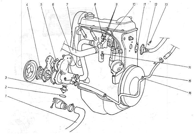
Pic. 2.5. Cooling system - 1.6 and 1.8 liter engines
1 - radiator / water pump pipe; 2 - thermostat cover washer; 3 - thermostat; 4 - front cover with blades; 5 - gasket; 6 - input channel to the engine housing; 7 - branch pipe of the head / radiator; 8 - thermal switch; 9 - gasket; 10 - outlet fitting to the radiator; 11 - gasket: 12 - outlet fitting from the head; 13 - temperature sensor; 14 - thermal switch; 15 - return pipe from the stove; 16 - the place of connection of the branch pipe from the surge tank.
d) To check the thermal switch, you need to disconnect the clamp of the end of the electrical connection, unscrew the bolts, remove the switch from the housing and plug the opening of the switch to stop the coolant from flowing out.
e) Having connected the thermometer to the ends of the thermal switch, gradually warm up the base of the switch in hot water. Resistance must be zero (those. internal contacts must be closed) at the following temperatures:
engine 1.1 - 65°С
engines 1.3 and 1.6 and 1.8 - 55°C
and) Resistance must be max (those. internal contacts must be open) at the following temperatures
engine 1.1 - 75°С
engines 1.3 and 1.6 and 1.8 - 65°C
If the switch is defective, it must be replaced with a new one. The heating element is deactivated when the engine reaches the normal operating temperature indicated above.
2. Heating of the drive manifold with coolant is carried out in order to improve the conditions for the evaporation of fuel flowing through the manifold.
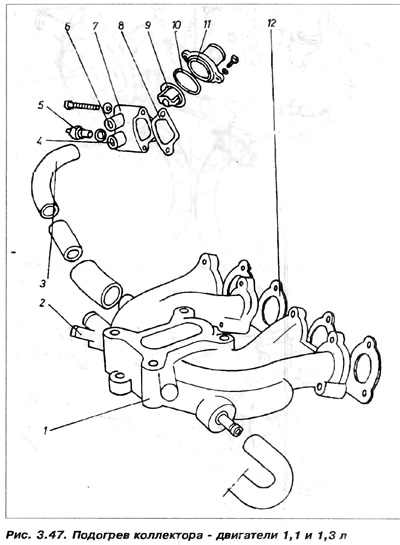
Heated coolant leaks from thermostat housing (engines 1.1 and 1.3, fig. 3.47) or from head outlet (engines 1.6 and 1.8). The liquid flowing through the manifold gives off heat to the walls, which heat the flowing fuel-air mixture.
Visitor comments