



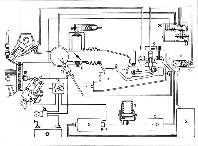
Figure 3.51. K-Jetronic injection system diagram
1 - differential measuring valve; 2 - air flow meter; 3 - fuel distributor; 4 - mixture composition adjustment bolt; 5 - fuel tank; 6 - fuel pump; 7 - pressure accumulator; 8 - fuel filter; 9 - pressure regulator; 11 - nozzle; 12 - idle speed adjusting bolt; 13 - battery; 14 - ignition switch; 15 - fuel pump shut-off switch; 16 - ignition distributor; 17 - cold start valve; 18 - Thermal time switch; 19 - additional air valve; 20 - engine heating valve.
(The original material is available on the portal www.VWMANUAL.ru)
Visitor comments