
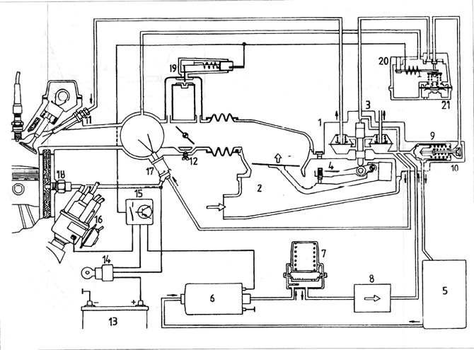
Pic. 3.51. Scheme of the K-Jetronic injection system
1 - differential measuring valve; 2 - air flow meter; 3 - fuel distributor; 4 - adjusting bolt of the composition of the mixture; 5 - fuel tank; 6 - fuel pump; 7 - pressure accumulator; 8 - fuel filter; 9 - pressure regulator; 11 - nozzle; 12 - idle speed adjusting bolt; 13 - battery; 14 - ignition switch; 15 - switch disconnecting the fuel pump; 16 - ignition distributor; 17 - cold engine start valve; 18 - thermal time switch; 19 - additional air valve; 20 - engine heating valve.
The idle speed is adjusted when the engine is warm.
2. Periodic maintenance of the fuel injection system covers checking the condition and reliability of the system and replacing the air filter cartridge at certain intervals.
A) Check the condition and protection of the elements of the reduced pressure system.
b) In case of malfunctions in the system, it is necessary to familiarize yourself with the contents of the paragraph in the table of malfunctions. However, first of all, carefully check the flexible pipes of the coupling system, fuses and relays for obvious damage.
V) If for any reason it is necessary to disconnect or remove part of the system, do so carefully to prevent debris from entering the system.
G) Regardless of the engine temperature, there is an overpressure in the system, so care must be taken when disconnecting the fuel pipes. The ignition must be turned off and the clamps of the wires supplying the electrical equipment must be removed from the battery poles.
d) Before disconnecting the fuel pipes, it is recommended to reduce the pressure in the system by slowly loosening the fuel supply pipe near the start valve and collect the fuel leaking from the connection with a rag.
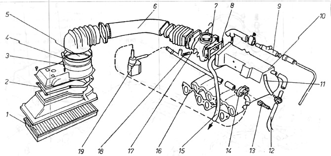
Pic. 3.52. Engine suction system with petrol injection
1 - air filter insert; 2 - gasket; 3 - mixture adjustment bolt (under the plug); 4 - plug 5 - air flow meter, 6 - suction pipe; 7 - throttle body, 8 - gasket; 9 - reduced pressure equipment for increasing the rotation speed; 10 - drive manifold; 11 - branch pipe to the fuel regulator; 12 - branch pipe to the servomechanism; 13 - electrical connection (black); 14 - additional air valve; 15 - branch pipe to the head; 16 - manifold gasket; 17 - O-ring type o-ring; 18 - idle speed adjusting bolt; 19 - idle speed control valve under load.
Visitor comments