



If the engine stalls after starting, switch 15, connected to the air flow meter plate, immediately switches off the pump
Fuel sucked from fuel tank 5 by pump 6 is supplied to fuel pressure accumulator 7. The task of the pressure accumulator is to maintain pressure in the fuel system after the engine is turned off so that the engine can be started again immediately.
Behind the pressure accumulator there is a fuel filter 8. The regulator 9 is connected to the fuel pressure accumulator and is integral with the fuel dosing equipment 3.
When the engine is switched off, the pressure regulator allows the fuel pressure to drop to the injectors and cuts off the fuel flow through the injectors 11. This prevents spontaneous ignition. The pressure regulator closes just below the opening pressure of the injectors and this pressure is then maintained by the pressure accumulator.
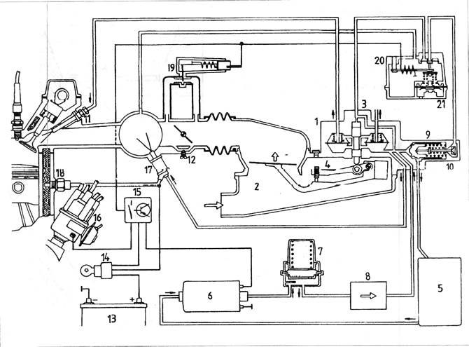
Figure 3.51. K-Jetronic injection system diagram
1 - differential measuring valve; 2 - air flow meter; 3 - fuel distributor; 4 - mixture composition adjustment bolt; 5 - fuel tank; 6 - fuel pump; 7 - pressure accumulator; 8 - fuel filter; 9 - pressure regulator; 11 - nozzle; 12 - idle speed adjusting bolt; 13 - battery; 14 - ignition switch; 15 - fuel pump shut-off switch; 16 - ignition distributor; 17 - cold start valve; 18 - Thermal time switch; 19 - additional air valve; 20 - engine heating valve.
Visitor comments