



Each measuring section has a differential pressure valve that ensures equal pressure on both sides of the section. Since the open length of the section does not affect the amount of pressure drop across the section, the amount of fuel flowing depends only on the open surface of the sections.
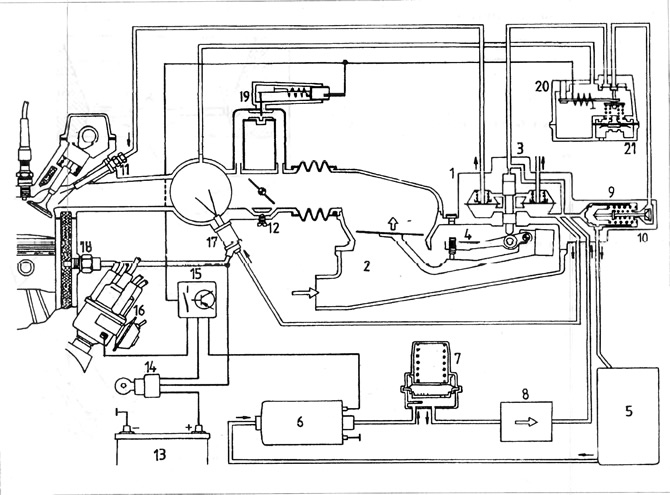
Figure 3.51. K-Jetronic injection system diagram
1 - differential measuring valve; 2 - air flow meter; 3 - fuel distributor; 4 - mixture composition adjustment bolt; 5 - fuel tank; 6 - fuel pump; 7 - pressure accumulator; 8 - fuel filter; 9 - pressure regulator; 11 - nozzle; 12 - idle speed adjusting bolt; 13 - battery; 14 - ignition switch; 15 - fuel pump shut-off switch; 16 - ignition distributor; 17 - cold start valve; 18 - Thermal time switch; 19 - additional air valve; 20 - engine heating valve.
The information is posted on this website [vwmanual.ru]
Visitor comments