
A) Disconnect the ground wire from the battery.
b) Remove air filter.
V) Disconnect the gas line.
G) Mark electrical wires with adhesive tape and then disconnect.
d) In the 2E2 carburetor, unscrew the hex bolt on the cover of the starting equipment.
e) Remove the low pressure pipes and label them.
and) Remove the fuel pipes.
h) Unscrew the three through-thread fixing bolts in the middle of the carburetor (pic. 3.12).
Pic. 3.12. Carburetor mount 2E2
1, 2, 3 diametric bolts. fixing the carburetor to the manifold
h) Remove the carburetor and close the intake manifold.
Installation
Attention: Since December 1984 the bolts holding the rubber collar are secured with a metal washer. If dismantling is necessary, tighten the bolts to a torque of 13 Nm, and then bend the metal washer. These washers can also be fitted to vehicles that have not previously had them.
4. Install the carburetor, paying attention to the washer and tighten the fastening bolts. Connect the electrical wires, paying attention to consistency with the previous designation.
l) Put on the fuel pipes and clamp them with belts.
m) Put on the low pressure hose.
n) Connect the wire to battery ground.
O) Install the tie rod and secure the rubber cover.
P) Put on the starting equipment cover and tighten the hex bolt.
R) Install the air filter.
With) Adjust idle speed
2. The steps for removing and inspecting the 2E2 carburetor are exactly the same. as for the carburetor 2EZ. Below are additional actions that differ from those in that paragraph.
3. Partial load channel heater assembly 27 (pic. 3.27) To test this assembly, connect a test light between the assembly's electrical wire plug and the positive battery terminal. Connect the assembly to ground. The control lamp must be lit. If it does not light, the assembly must be replaced.
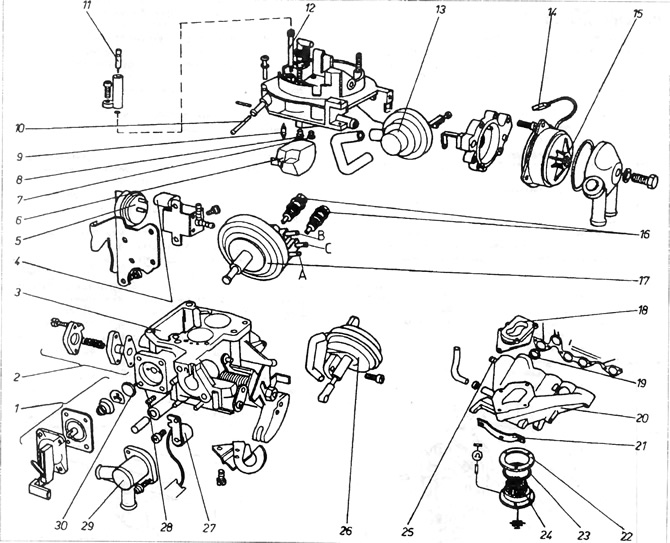
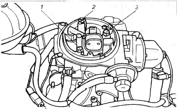
Pic. 3.27. Carburetor 2E2
1 - accelerator pump assembly; 2 - mixture enrichment valve with partial throttle opening (Once removed, the valve must be replaced with a new one); 3 - float chamber; 4 - valve that controls the disconnection of the idle system and at speeds higher than the idle speed; 5 - thermo-temporary valve; 6 - float; 7 - main jet of the first pass; 8 - main jet of the second pass; 9 - needle valve; 10 - filter; 11 - adjusting bolt of the exhaust gas composition; 12 - idle jet; 13 - servomotor; 14 - plug; 15 - automatic start equipment cover; 16 - valves for adjusting the idle speed (lower only available with four output servomotor); 17 - servomotor with three outputs; 18 - A, B, C - fittings for connecting the servomotor (four outputs have servomotors in cars with automatic transmission); 18 - shock-absorbing cuff; 19 - additional gasket type o-ring (boxing ring) between the manifold and the head, 20 - drive manifold; 21 - holder; 22 - washer; 23 - gasket; 24 - mixture heater; 25 - fitting for connecting the servo; 26 - servomotor controlling the opening of the second passage; 27 - heater of the partial throttle opening channel; 28 - adjusting bolt; 29 - valve cover with coolant fittings; 30 - mushroom valve.
The current to the heater is supplied through a thermal switch. It can be checked by connecting a pressure gauge and clamping it. At temperatures below 55°C, the thermometer should show "0", and only at temperatures above 65°C - infinity. If it does not, then it is damaged and needs to be replaced.
When installing the heater assembly, make sure that it is well connected to the carburetor ground
4. The starting equipment servomotor serves to open and hold the diaphragm in a certain position immediately after starting the engine. This prevents excessive enrichment of the mixture beyond the flammability limit.
After starting the engine, the increasing vacuum acts on the diaphragm of the servomotor and causes the diaphragm to open slightly at a certain angle, tensing the spring. It can be checked by doing the following
A) Remove air filter cover
b) Start the engine and leave it to idle.
V) Try manually closing the aperture. If it closes easily all the way, the servomotor is damaged. In a normally working servomotor, during the closing of the diaphragm, a certain resistance will appear when there is a gap of 5 mm between the edge of the diaphragm and the carburetor neck.
5. Accelerator pump (carburetor removed):
To check the accelerator pump, the carburetor must be removed. A vacuum pump and a 20 mm M8 bolt will be needed.
A) Disconnect the low pressure elastic pipes from the servomotor with three or four outlets 17, then connect the vacuum pump to port A and close port B (and additionally C with a servomotor with four outputs). Reduce the pressure with the pump to keep the servo pushrod in the contraction position (decrease) move. There is a gap between bolt 3 and pusher 5 (pic 3.28 and 3.29)
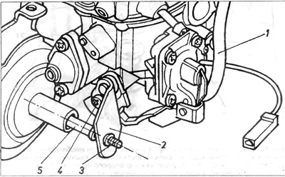
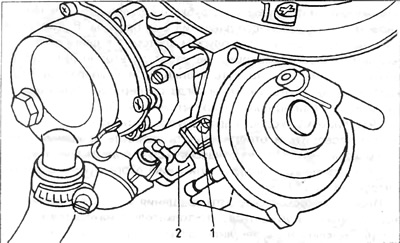
Pic. 3.28. Carburetor 2E2
1 - reduced pressure pipe; 2 - cam plate; 3 - adjusting bolt for the speed of rotation of the engine at suction; 4 - fixing screw; 5 - pusher of the three-output servomotor.
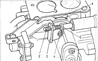
Pic. 3.29. Carburetor 2E2
1 - reduced pressure pipe; 2 - cam plate; 3 - adjusting bolt for the speed of rotation of the engine at suction; 4 - fixing screw; 5 - servomotor pusher with three outputs; 6 - designation of the direction of rotation of the plate: (+) - increasing the portion, (-) - portion reduction.
b) Turn the lever of the starting equipment and insert an M8x20 mm bolt between it and the carburetor so that the lever remains in an inclined position
V) Hold the carburetor over a funnel inserted into the measuring cylinder, and then fully open and close the throttle 5 times. The throttle must be opened quickly and closed slowly.
Each throttle opening stroke must last at least 3 seconds. Divide the amount of fuel collected in the measuring cylinder by 5 and check whether the obtained flow rate of the accelerator pump is consistent with that indicated in the technical data.
If adjustment is necessary, loosen screw 4 and turn cam plate 2 in the desired direction to increase or decrease the injection volume (see designation 6 fig. 3.29). Finally tighten screw 4 and in this position protect it with paint.
6. Throttle adjustment of the first pass of the carburetor:
The throttle stop bolt is set at the factory and should not be changed under normal conditions. Only if the installation is inadvertently disturbed, the bolt must be reinstalled as follows:
A) Rotate start cam 2, fig. 3. 30 until the throttle control rod is out of contact.
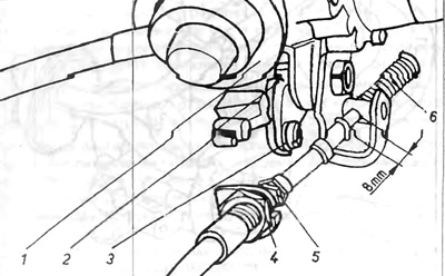
Pic. 3.30. Throttle adjustment 1st pass 2E2
1 - servomotor; 2 - launch equipment cam; 3 - lever; 4 - adjusting nut of the metal cable protection 8 mm spring bend during checking the adjustment of the carburetor cable (Automatic transmission).
b) Lock the start cam in this position with a screwdriver on the lever.
6. Remove all low-pressure flexible pipes from the servomotor with three outlets and plug connection B (pic. 3.27).
G) Connect a low pressure pump to port A (rarefied air) and reduce the pressure so that the diaphragm is held in the switching position.
d) Check if there is a gap between the suction speed adjusting screw 3 and the pusher 5 of the servomotor (pic. 3.29).
e) Loosen adjusting screw 1 until there is a gap between adjusting screw and stop 2 (pic. 3.31).
Pic. 3.31. Throttle adjustment 1st pass
1 - adjusting screw, 2 - limiter.
e) Screw in the adjusting screw until it mates with the limiter.
and) Screw in the adjusting screw ¼ turn and seal the thread with paint.
7. The 2-way throttle setting is factory set and should not be changed. If for any reason the setting of the adjusting bolt has changed, it must be corrected as follows:
Open the throttle fully and hold it in this position by inserting a wooden lever or something similar between it and the neck (pic. 3.32).
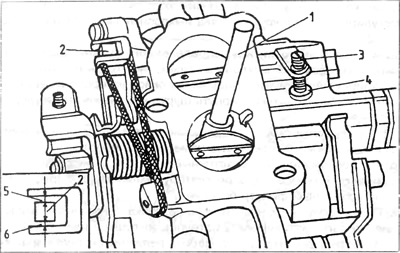
Pic. 3.32. Throttle adjustment 2nd pass 2E2
1 - throttle lock; 2 - blocking lever, 3 - buffer bolt; 4 - buffer; 5 and 6 - gaps on both sides of the blocking lever.
Using a rubber band, pre-tighten the bopt blocking the second pass throttle lever, then unscrew the buffer bolt to a position where there is a gap between the buffer bolt and the buffer 4. Screw in the bolt until it touches the buffer. This point of contact of the bolt with the buffer can be captured by inserting a piece of thin paper between the bolt and the stop. When the paper begins to be compressed by these two elements, this means that the point of contact has been reached. From this position, screw in the buffer bolt another ¼ turn and secure it with paint. Close two throttles and measure gaps 5 and 6 (pic. 3.32).
The gaps should be:
5 - 0.3...0.5 mm
6 - 0.9...1.1 mm
If the gaps are different, these levers must be bent.
Visitor comments