
First stage
A) Remove the automatic start equipment cover.
b) Rotate the diaphragm control lever clockwise and hold it in this position with the rubber band.
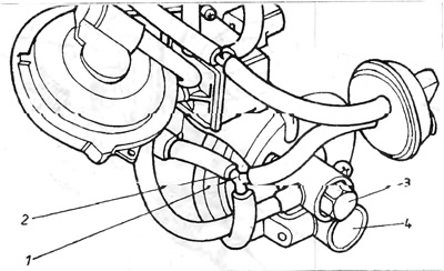
V) Remove the reduced pressure flexible pipe from the carburetor 1 (pic. 3.27).
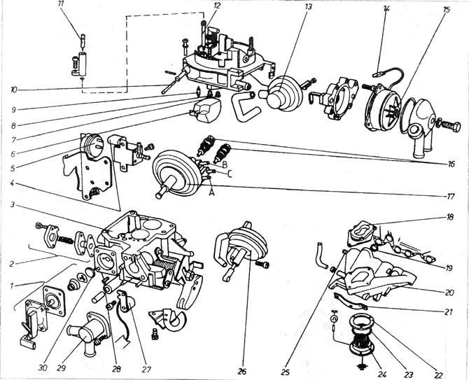
Pic. 3.27. Carburetor 2E2 1 - accelerator pump assembly; 2 - mixture enrichment valve with partial throttle opening (Once removed, the valve must be replaced with a new one); 3 - float chamber; 4 - valve that controls the disconnection of the idle system and at speeds higher than the idle speed; 5 - thermo-temporary valve; 6 - float; 7 - main jet of the first pass; 8 - main jet of the second pass; 9 - needle valve; 10 - filter; 11 - adjusting bolt of the exhaust gas composition; 12 - idle jet; 13 - servomotor; 14 - plug; 15 - automatic start equipment cover; 16 - valves for adjusting the idle speed (lower only available with four output servomotor); 17 - servomotor with three outputs; 18 - A, B, C - fittings for connecting the servomotor (four outputs have servomotors in vehicles with automatic transmission); 18 - shock-absorbing cuff; 19 - additional gasket type o-ring (boxing ring) between the manifold and the head, 20 - drive manifold; 21 - holder; 22 - washer; 23 - gasket; 24 - mixture heater; 25 - fitting for connecting the servo; 26 - servomotor controlling the opening of the second passage; 27 - heater of the partial throttle opening channel; 28 - adjusting bolt; 29 - valve cover with coolant fittings; 30 - mushroom valve.
Connect a hand vacuum pump to port A (pic. 3.27).
G) Remove the reduced pressure connection from the reduced pressure flexible tube 4 (pic. 3.33). Do not pinch the tube.
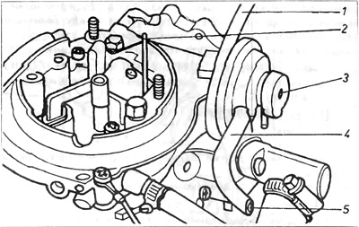
Pic. 3.33. 2E2 Startup Aperture Gap Adjustment 1 - reduced pressure pipe; 2 - drill; 3 - adjusting bolt; 4 - reduced pressure pipe; 5 - the end of the reduced pipe. pressure
d) Create a reduced pressure in the range of 200-300 mbar.
e) Check start diaphragm clearance by gripping a drill of a certain diameter (pic. 3.33).
e) If the gap does not correspond to the specifications, adjust it by turning the hex bolt 3 (pic. 3.33). After completing the adjustment, protect the adjusting bolt with paint.
Second phase
A) Seal the end of the pipe 5 with a suitable plug (pic. 3.33).
b) Reduce pressure to 200 mbar.
V) Recheck diaphragm clearance using drill 2 (pic. 3.34).
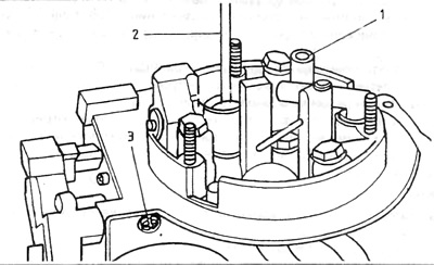
Pic. 3.34. Startup Aperture Gap Adjustment - Second Stage 2 - drill, 3 - adjusting bolt
G) If the characteristics of the carburetor do not correspond to the technical data, adjust it by turning the bolt 3 (pic. 3.34).
d) After completing the adjustment, protect the bolt with paint.
e) The signs on the cover of the launch equipment must match - one continues the second.
d) Servo motor with three or four outputs. Four output servo motor is used in vehicles with automatic transmission or air conditioning.
To test the operation of this servomotor, a rarefied air pump will be needed.
A) Disconnect the low pressure flexible pipes from the servomotor and connect the vacuum pump to port A (pic. 3.27).
Relieve pressure to tighten the servo pushrod to the position "switched off" and then measure the length of the protruding part of the pusher, which should be 8.5 mm.
b) To check the over-cut-off point (only on models with automatic transmission), it is necessary to remove the plug from the end of the reduced pressure pipe C, then increase the vacuum using a vacuum pump. This should cause the pusher, servo to move to the over-cut point". Measure the length of the protruding part of the pusher. The pusher should now protrude 1 mm from the servomotor and this amount should not change within 1 minute.
V) If the length of the protruding part of the lever is abnormal or does not hold for the required period of time, this indicates that the servo motor with three or four outputs is leaking and needs to be replaced.
10. Reduced pressure servomotor assembly 2 passages This equipment is installed on 1.6 engine models with a manual transmission, as well as with a 1.8 engine and automatic transmission from August 1984. The purpose of this equipment is to slightly delay the opening of the second passage of the carburetor when the coolant temperature is less than 18°C. The delay is carried out by connecting the control servomotor to the atmosphere, opening the second passage with a thermopneumatic valve 5, and a flange in the pipe connecting the valve 5 and the reduced pressure servomotor of the 2nd passage. In 1.6 engines, the flange is indicated in blue, and in 1.8 engines, in yellow. Check if the second branch pipe on the valve fitting is clogged 5 purge the valve. At a temperature of +18°C the valve must be open, and when the temperature exceeds +28°C, the valve must be closed (pic. 3.27).
11. Idle speed adjustment.
To check and adjust the idle speed, you must read the contents of paragraph 23 16 and proceed as described in this paragraph, taking into account the following differences:
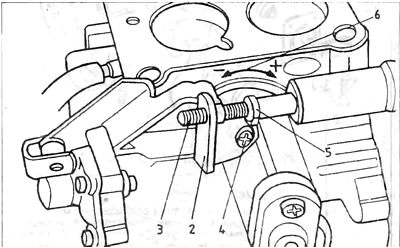
A) Before checking the idle speed, you must first make sure that the pusher 5 is in the position "switched off", and the adjusting bolt of the engine rotation speed on suction is docked with the pusher 5 Otherwise, it is necessary to warm up the engine well (pic. 3.28).
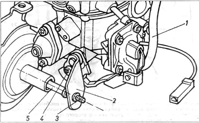
Pic. 3.28. Carburetor 2E2 1 - reduced pressure pipe; 2 - cam plate; 3 - adjusting bolt for the speed of rotation of the engine at suction; 4 - fixing screw; 5 - pusher of the three-output servomotor.
b) If adjustment is necessary, turn idle speed adjusting valve 3 and exhaust gas composition adjusting screw 11 (pic. 3.35 and 3.27).
Pic. 3.35. Carburetor - 2E2 1 - tee; 2 - reduced pressure pipe; 3 - adjusting idle speed bolt; 4 - adjusting bolt speed of rotation xonocforo stroke under load.
If it is difficult to reduce the carbon monoxide content in the exhaust gases to a certain level, it is necessary to unscrew the carbon monoxide content adjusting screw and clean its tip, then screw in the screw and adjust.
12. Suction motor speed control:
A) Connect a speed meter to the engine
b) Seal the low pressure flexible pipe from the carburetor to the temperature controller 3 (pic. 3.3).
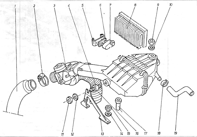
Pic. 3.3. Air Filter Assembly - 1.6L and 1.8L Engines 1 - suction pipe; 2 - clamping belt. 5 - temperature controller; 4 - rubber shock absorber; 5 - temperature sensor bracket; 6 - temperature sensor; 7 - filter insert; 8 - nut securing the body; 9 - washer; 10 - nut; 11 - washer; 12 - bracket; 13 - washer; 14 - nut; 15 - suction pipe of warm air; 16 - remote bushing; 17 - clamping belt; 18 - crankcase air outlet pipe.
If the air filter has been removed:
V) Remove the tee 1 from the low-pressure flexible fitting 2 and seal the fitting with a plug (fig 3.35)
G) Start the engine and check the suction speed of the engine.
d) If the rotation speed does not correspond to the technical data, adjust by turning the adjusting bolt 3 (pic. 3.28).
e) Reconnect the pressure reducing hose and (if necessary) adjust idle speed.
13. Engine idle speed under load in car models with automatic transmission can be checked as follows. First of all, in addition to the prerequisites required when checking the idle speed setting, the handbrake must be fully applied and the wheels must be blocked with wedges.
A) Start the engine, turn on the air fan at full speed, turn off the high beams and the heated rear window.
The person sitting in the car must press the brake pedal, and then select position D in the gearbox control b) Check whether the adjusting bolt 3 is on the pusher 5 and the engine speed is at least 800 rpm. Adjust speed if necessary, change valve setting 4 (pic. 3.36). This valve is only available on vehicles with automatic transmission or air conditioning.
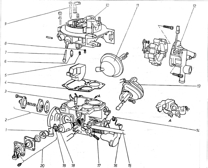
Pic. 3.36. Carburetor 2EZ 1 - mushroom valve; 2 - mixture enrichment valve at partially open throttle; 3 - the injector of the injection pump must supply fuel in the direction chosen in the carburetor neck; 4 - cover gasket; 5 - main jet - passage 1; 6 - needle valve 7 - strainer; 8 - main jet - passage 2; 9 - idle jet; 10 - economizer tube; 11 - launch equipment servomotor; 12 - launch equipment cover; 13 - servomotor controlling the opening of the second passage; 14 - adjusting bolt; 15 - idle speed adjustment; 16 - lever, 17 - adjusting bolt of the composition of the mixture; 18 - idle shut-off valve; 19 - limiting screw 20 - accelerator pump assembly.
V) Disconnect the tee 1 from the reduced pressure flexible pipe 2 and plug the pipe. Connect a speed meter to the engine. Start the engine and check that the suction speed of the engine corresponds to the value specified in the technical data.
If the speed value does not correspond to the specified one, it is necessary to adjust it by turning the adjusting bolt 3 (pic. 3.29).
Pic. 3.29. Carburetor 2E2 1 - reduced pressure pipe; 2 - cam plate; 3 - adjusting bolt for the speed of rotation of the engine at suction; 4 - fixing screw; 5 - servomotor pusher with three outputs; 6 - designation of the direction of rotation of the plate: (+) - increasing the portion, (-) - portion reduction.
After completing the adjustment, protect the screw with paint. Remove the plug from the flexible pipe and reconnect the tee and check that the idle speed is 900-1000 rpm.
Visitor comments