
A) Remove the air filter assembly.
b) Connect a speed meter to the engine.
V) Rotate the suction speed cam 1 so that the adjusting screw 2 is on the highest tooth of the cam (pic. 3.19).
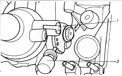
Pic. 3.19. Carburetor 1VZ
1 - suction rotation speed cam; 2 - adjusting bolt.
G) Start the engine without depressing the accelerator pedal and record the intake speed.
d) If the suction speed does not match the specifications, remove the safety cap and adjust the speed by turning the adjusting screw 2 (pic. 3.19).
2. The position of the adjusting screws is shown in fig. 3.20A and 3.20V.
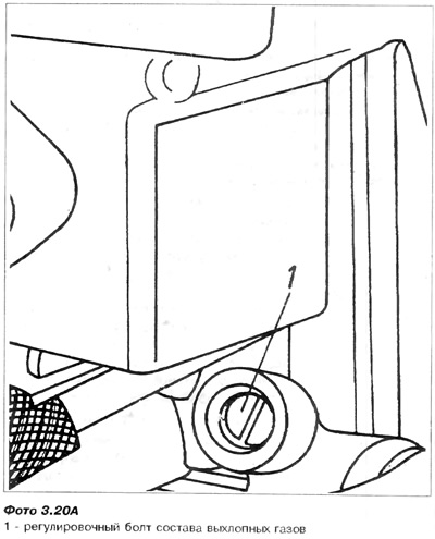
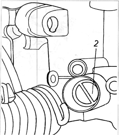
Photo 3.20B. Carburetor 1VZ
2 - idle speed adjusting bolt.
3. Adjustment of the gap of the aperture diaphragm.
A) Remove the waterbox cover and bimetallic spring assembly of the starting equipment. No need to disconnect the electrical wire and elastic water pipes from the cover assembly,
b) By turning the throttle, set the rotation speed cam on the suction 1 so that the adjusting bolt 2 is on the highest tooth (pic. 3.19).
V) Pushing the diaphragm gap adjusting screw 1 with a screwdriver, move the diaphragm control lever towards the reduced pressure servomotor assembly to the stop (pic. 3.21).
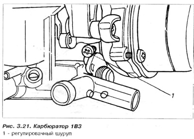
G) In this position of the lever, check the gap between the edge of the diaphragm and the wall of the carburetor neck using a 4.3 mm drill.
d) If necessary, adjust the clearance by turning screw 1.
e) After completing the adjustment, install the starter equipment cover. The designation on the cover must match the corresponding designation on the body of the launching equipment.
4. Starting equipment servomotor assembly.
The operation of the reduced pressure servomotor assembly can be checked as follows:
A) With the air filter assembly removed, start the engine at idle.
b) Close the trigger diaphragm manually and observe the servomotor operation. If the diaphragm can be easily closed up to a gap of about 4 mm, and then a certain resistance is felt, then the servomotor is working correctly. If the diaphragm can be completely closed without any resistance, this indicates damage to the diaphragm of the servomotor or a leak in the reduced pressure system.
V) If the diaphragm is ruptured or torn, it must be replaced.
G) If the diaphragm is normal, it is necessary to check the reduced pressure at the entrance to the servomotor.
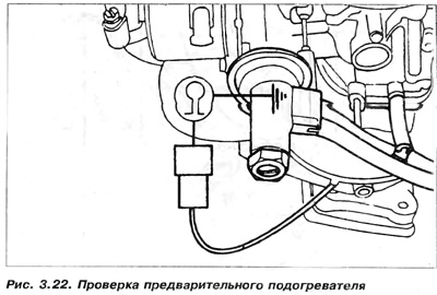
5. Preheater in drive manifold:
6. The drive manifold has a pre-heater. It serves to preheat the air-fuel mixture flowing through the manifold. This is done to facilitate the evaporation of fuel at low temperatures. Its operation can be checked as follows:
A) Disconnect the preheater assembly wiring harness from the connection near the carburetor. This is the sub-GO1 wire to the drive manifold at the bottom.
b) Check the resistance between the end of the preheater wire and ground. It should be 0.25-0.50 Ohm. If the resistance is different, the preheater assembly must be replaced with a new one (pic. 3.22).
6. Thermal switch:
Two thermal switches screwed into the engine cooling system. control the energization of the auto-suction heater and drive manifold pre-heater assembly based on coolant temperature. Red controls automatic suction, and transparent controls the manifold preheater.
The operation of the thermal switches can be checked using a test lamp (pic. 3.22)
A) Before removing the switch on a cold engine, disconnect the wiring connections and turn on a test light in series between the end of the electrical wire supplying the thermal switch and the end of the thermal switch. When the ignition is on, the test light should be on. If the light does not illuminate, the switch is faulty and needs to be replaced. If the light is on, remove the switch and hang it in a container of water. The control light must be connected to the plus of the battery and the end of the thermal switch, and the minus of the battery to the body of the thermal switch. Heat the water, the light should turn off when the temperature is between 30-40°C (red switch) or between 50-55°C (transparent switch), otherwise the corresponding switch must be replaced.
Visitor comments