
2. Remove the screws from the carburetor cover.
3. Raise the carburetor cover and remove the gasket.
4. Raise the locking element (above the float axis) and remove the float from the float chamber of the carburetor.
5. Clean the float chamber with fuel.
6. If necessary, to further disassemble the carburetor, use fig. 3.13.
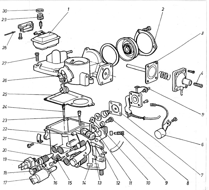
Pic. 3.13. Carburetor 31 PIC-7
1 - float; 2 - fixing ring; 3 - diaphragm of the servomotor, 4 - adjusting screw of the diaphragm gap; 5 - adjusting bolt flow rate of the accelerator pump; 6 - heater of the partial throttle opening channel; 7 - pump diaphragm; 8 - additional fuel jet; 9 - idle jet; 10 - fungal valve; 11 - nozzle of the accelerator pump; 12 - fitting for connection with the air filter temperature controller; 13 - adjusting bolt for diaphragm clearance; 14 - designation of the type of carburetor; 15 - adjusting bolt for the composition of the mixture, 16 - main fuel jet; 17 - side air valve; 18 - cork; 19 - thermal switch of the heater of the channel of partial opening of the throttle; 20 - idle speed adjusting bolt; 21 - fitting for connecting the reduced pressure pipe of the ignition timing regulator; 22 - roller of the lever for uniform operation of the engine; 23 - air braking jet with emulsion tube; 24 - additional air jet; 25 - gasket; 26 - eccentric kingpin; 27 - carburetor cover bolt; 28 - float axis; 29 - needle valve; 30 - adjusting washer for the needle valve
7. After removing the side air valve 17 can be checked as follows. Push a needle into it 3-4 mm. then connect the power and touch the body to the mass, while a crack should be heard, and the kingpin should move forward.
8. If the carburetor is equipped with a main jet shut-off valve (looks like valve 17), it can be checked in the same way. When the voltage is connected, a crackling sound should be heard.
9. The idle shut-off valve is solenoid operated. It cuts off the fuel supply to the system and the occurrence of spontaneous combustion after the engine is turned off. There is another reason for using a shut-off valve.
In an engine without a shut-off valve, from the moment the key is turned until the engine stops, fuel is wasted from the idle system. When the engine is turned off, the fuel evaporates and enters the environment, polluting the environment.
The valve is screwed into the side wall of the carburetor body just below the idle adjustment bolts and can be checked in the following way:
After switching on the ignition, the valve should make an audible crack. This indicates the advancement of the kpapan needle through the electromagnet at the moment the voltage is applied. The valve must be removed if it does not work properly.
10. The carburetor fitted to 1.1 and 1.3 engine models has an electrical heater element installed to heat the part load channel. It is located below the launch system housing next to the accelerator pump. To check the heating element, it is necessary to disconnect its wire from the clamp on top of the carburetor.
A test lamp must be connected between the heating element clamp and the positive pole of the battery. The lamp must light up, otherwise the heating element is broken and must be replaced with a new one.
11. Installation of the carburetor is carried out in the reverse order of removal. All gaskets and rubber o-rings must be replaced. Adjust carburetor.
12. To adjust the diaphragm clearance of the triggering equipment, you must:
A) On manual choke PIC carburetors, fully remove the choke cable tip to set the choke speed cam to its highest position. Remove the cover with the bimetal spring from the body of the starting equipment (pic. 3.13).
b) On automatic choke PICT carburetors, remove the starting equipment water chamber cover with the bimetal spring assembly and close the diaphragm.
V) Press the pin 1 of the diaphragm inward to its limiter in the housing (pic. 3.14).
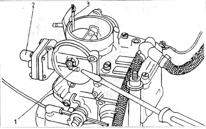
Pic. 3.14. Diaphragm clearance check - PIC and PICT carburetors
1 - diaphragm pin; 2 - body of the diaphragm gap adjusting bolt; 3 - drill.
G) Using a drill 3 of the appropriate diameter, check the gap between the upper face of the diaphragm plate and the neck wall (pic. 3.14).
d) If the gap exceeds the limits specified in the technical data, adjust the gap by tightening the diaphragm gap adjusting bolt 4 (pic. 3.13)
e) In building 2 (pic. 3.14) After adjustment is complete, install the starter cover and bimetal spring assembly, ensuring that the bimetal spring is correctly positioned on the diaphragm lever. Install the cover like this. so that the designation on the cover matches the designation on the carburetor body.
Visitor comments