
2. Unscrew and remove the screws securing the carburetor cover, then carefully remove the cover so as not to break the gasket. After that, you can remove the corresponding elements from the cover and the main body of the carburetor, using fig. 3.36.
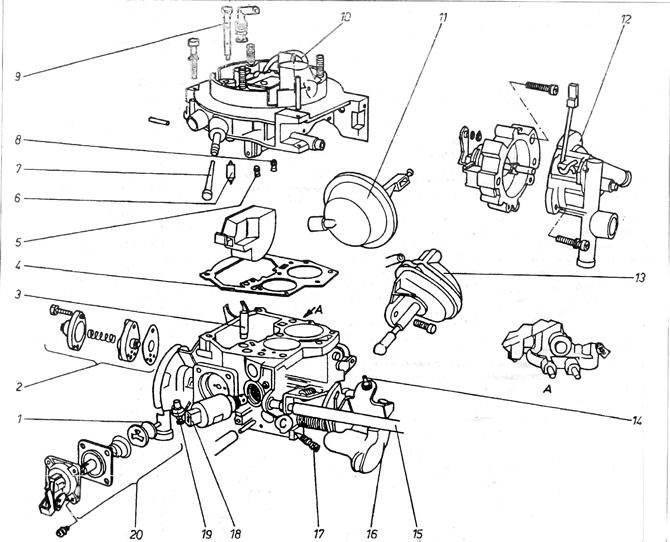
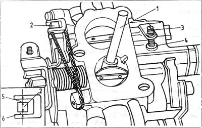
Pic. 3.36. Carburetor 2EZ
1 - mushroom valve; 2 - mixture enrichment valve at partially open throttle; 3 - the injector of the injection pump must supply fuel in the direction chosen in the carburetor neck; 4 - cover gasket; 5 - main jet - passage 1; 6 - needle valve 7 - strainer; 8 - main jet - passage 2; 9 - idle jet; 10 - economizer tube; 11 - launch equipment servomotor; 12 - launch equipment cover; 13 - servomotor controlling the opening of the second passage; 14 - adjusting bolt; 15 - idle speed adjustment; 16 - lever, 17 - adjusting bolt of the composition of the mixture; 18 - idle shut-off valve; 19 - limiting screw; 20 - accelerator pump assembly.
Do not change the setting of the full throttle limiter and the carburetor second pass throttle adjusting bolt.
3. Clean the internal elements of the carburetor. To clean the jets from debris, do not push the jets with wiring, but perform this operation with compressed air.
4. Removing the mixture enrichment valve with a partially open throttle 2 makes it necessary to replace it with a new one (pic. 3.36).
5. To check the level of the shut-off valve 18, it is necessary to connect power directly from the battery to it. After applying voltage to the valve, a crackling sound should be heard.
6. The carburetor is installed in the reverse order of removal. At the same time, all gaskets and rubber rings are replaced. Then the necessary checks and adjustments are made.
7. To check the diaphragm clearance of the starting equipment, it is necessary to remove its cover 12 (pic. 3.36).
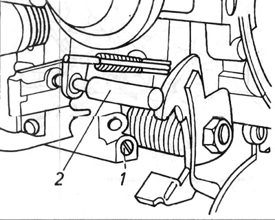
Rotate the throttle and adjusting cam 3 of the suction speed of the engine so that the adjusting screw 1 rests on the topmost tooth of the cam 2 (pic. 3.37) Then screw in the adjusting screw 1 until it stops in the direction of the servomotor of the starting equipment, then check the gap between the diaphragm of the starting equipment and the neck wall using a drill of the appropriate diameter. If necessary, it must be adjusted by turning the adjusting bolt 1 until the normal clearance is obtained.
Pic. 3.37 Diaphragm clearance adjustment - carburetor 2ЕЗ
1 - adjusting bolt; 2 - the topmost cam tooth; 3 - cam.
8. The flow rate of the accelerator pump is checked as follows:
A) Remove the carburetor from the vehicle and fill the float chamber with fuel to the correct level.
b) Position the carburetor horizontally above the measuring vessel (float chamber must be filled with fuel). To do this, it is necessary to connect an elastic pipe 1 m long to the carburetor drive fitting. The pipe is filled with fuel using a syringe, and its upper end is suspended vertically above the carburetor.
V) Hold suction speed adjusting bolt 1 away from cam 2 and smoothly open and close throttle 6 times (pic. 3.36).
Open the throttle with a strong but smooth movement, and the time intervals between individual strokes should be 3 seconds.
G) Measure the amount of fuel collected, divide it by 6 and compare the resulting value with the technical data
d) If the value obtained does not correspond to the required value, it is necessary to adjust the amount of fuel injected by the pump by loosening the blocking bolt 1 and turning the control cam 2 clockwise to reduce the amount of fuel - B.
e) Repeat this experiment after clamping the blocking cam, and if the amount of fuel received is correct, install the carburetor as described above.
9. In order to test the starting equipment, connect a test light between the positive battery terminal and the electrical equipment. The test light must be on, otherwise the starter hardware is faulty and needs to be replaced
It is necessary to pay attention to the fact that the designations on the cover and the body of the automatic starter equipment match.
10. Cam start equipment:
A) Remove the carburetor from the vehicle and check that the diaphragm clearance is correct.
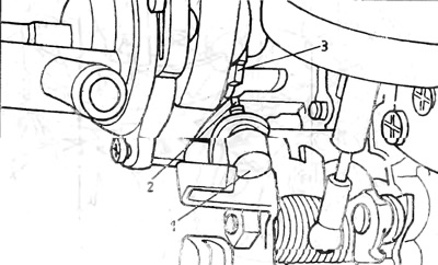
b) Connect the vacuum pump to the servomotor as described above and create and maintain a vacuum of approximately 300 milliator (pic. 3.42).
Pic. 3.42. Checking the sealing of the starting equipment servomotor
2 - servomotor; 3 - rarefied air pipe
V) Open the throttle wide enough so that the suction speed adjusting bolt 1 is out of contact between the teeth and start cam 2 (pic. 3.39).
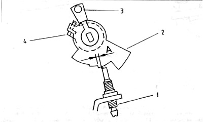
Pic. 3.39. Launch equipment cam - 2EZ
1 - adjusting bolt for suction speed; 2 - cam.
G) Carefully press down on the diaphragm lever 2 and 3 and release the throttle. The suction speed bolt 1 must be on the topmost tooth of cam 2 so that Dimension A is 0.5 mm (pic. 3.39).
d) If dimension A does not correspond to the normal value, adjust it by bending lever 4 (pic. 3.39).
e) After completing the adjustment, disconnect the vacuum pump and connect the reduced pressure pipe.
e) Install the carburetor on the car.
11. The starting equipment servomotor can be checked when it is removed from the carburetor, but since this requires a vacuum pump and measuring device, it is best to have this work done by a Volkswagen workshop. The servomotor can also be checked when the carburetor is installed on the engine.
A) The air filter must be removed.
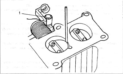
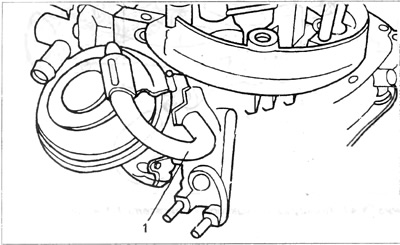
b) Start the engine and stop it from idling, then manually close the diaphragm of the starting equipment 1 until noticeable resistance. At this point, the gap should be approximately 4 mm. If the size is not normal, you need to adjust the gap of the trigger diaphragm (pic. 3.41).
Pic. 3.41. Aperture clearance adjustment - 2ЕЗ
1 - diaphragm launch equipment.
V) If there is not the slightest resistance in the rarefied air system, then the system is leaking or the membrane of the rarefied air servomotor is damaged.
G) If the servomotor is defective, all rarefied air connection connections must be checked for reliability, as well as the connections themselves for cracks and damage.
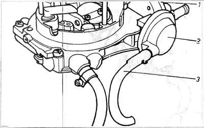
d) Disconnect the flexible tube 3 and connect the vacuum pump to the servomotor 2 in its place. Create an air vacuum in the servomotor chamber equal to 300 mbar.
e) Check if the vacuum is maintained for 2 minutes. If the vacuum disappears sooner, the servomotor must be replaced.
e) Disconnect the vacuum pump from the servomotor and reinstall the reduced pressure pipes.
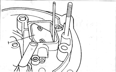
12. Throttle adjustment 2 passes completed but must not be changed. If for any reason the fixation of the adjusting bolt is changed, the adjustment is carried out as follows: open the throttle fully and hold it in this position by inserting a wooden lever or something similar between it and the neck (pic. 3.32).
Pic. 3.32. Throttle adjustment 2nd pass 2E2
1 - throttle lock; 2 - blocking lever, 3 - buffer bolt; 4 - buffer; 5 and 6 - gaps on both sides of the blocking lever.
Using a rubber band, pre-tighten the lever that blocks the throttle of the second pass, then unscrew the buffer bolt 3 to a position where there is a gap between the locking bolt and the stopper 4. Screw the bolt until it mates with the stopper (buffer). This point of contact with the stopper can be determined by inserting a piece of thin paper between the bolt and the stopper. When the paper begins to shrink between these two elements, it means that the point of contact has been reached. From this position, screw in the locking bolt another ¼ turn and secure it with paint.
Close the two throttles and measure the gaps of the blocking levers 5 and 6. These gaps should be equal to:
5 - 0.3...0.5 mm
6 - 0.9... 1.1 mm
If the gaps are different, these levers must be bent accordingly.
13. Rarefied air servomotor of the 2nd pass of the carburetor:
A) Connect the vacuum pump to the reduced pressure connection 1 and create a slight vacuum in the servomotor and the connection. If the reduced pressure reading from the meter disappears noticeably within about 2 minutes, the reduced pressure tube and servomotor are damaged and must be replaced.
14. Throttle lock 2nd pass carburetor:
A) Make sure the second pass throttle is closed and properly adjusted.
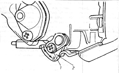
b) Check dimensions A and B between the second pass throttle lever 1 and its control forks 2 (pic. 3.44).
A - 0.5 mm B - 0.3 mm
If these values require adjustment, it is necessary to carefully bend the shoulders of the snare 2.
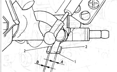
Pic. 3.44. Throttle Lever 2nd Pass
1 - lever; 2 - lever forks.
15. Throttle clearance:
A) Remove the carburetor as described above, unscrew it and install the suction speed bolt on the cam tooth itself 3 (pic. 3.37).
b) Measure throttle clearance with a drill. If it does not correspond to the technical data, adjust it by screwing in and out the speed adjusting bolt 1 (pic. 3.45).
Pic. 3.45. Throttle gap adjustment - 2EZ
1 - adjusting screw
V) Recheck the clearance. If it matches the specifications, install the carburetor as described above.
16. Adjusting the idle speed - 2EZ:
A) To check and adjust the idle speed setting, proceed as described (pic. 3.46).
Pic. 3.46. The position of the adjusting bolts - 2EZ
1 - adjusting bolt of the exhaust gas composition; 2 - idle speed adjusting bolt.
17. Adjusting the speed of the suction motor on a hot engine:
A) Remove air filter.
b) Plug the flexible pipe from the air filter temperature regulator.
V) Restart the engine and open the throttle slightly to obtain an engine speed of approximately 2500 rpm. Push the suction speed cam up to its limiter, then release the throttle so that the adjusting bolt 1 is on the second highest tooth of the suction speed cam 2 (pic. 3.39).
In this position, the suction rotation speed must be equal to the speed given in the technical data. If the value does not correspond to the technical data, it is necessary to turn the adjusting bolt in the desired direction to obtain this value. Please note that this bolt may have a safety cap.
G) Remove the plug from the temperature controller pipe and install the air filter.
Pic. 3.43. Vacuum air servomotor (reduced pressure) 2nd pass - 2EZ
1 - reduced pressure pipe (rarefied air).
Pic. 3.40. Accelerator pump adjustment - 2EZ
1 - blocking screw; 2- control cam.

Pic. 3.38. Diaphragm clearance adjustment - carburetor 2EZ
1 - adjusting bolt; 2 - diaphragm lever.
Visitor comments