
English Русский
Български
Беларускі
Український
Српски
Hrvatski
Română
Polski
Slovenský
Magyar
  |  Articles  |  Sitemap  |  Contacts  |    |
Car maintenance Ford Car maintenance Hyundai Car maintenance Chevrolet Car maintenance BMW Car maintenance Audi Car maintenance Opel Car maintenance AvtoVAZ
VWmanual.ru


Main   Passat   Golf   Polo   Touareg   Tiguan   Sharan   Transporter   Others  
LT 28 (1975-1991) LT 2D (1996-2003) Beetle (1960-1986) Caddy 3 (2003-2010)

Carburetor — adjustment (VW Lt 28)

  • Main
  • Volkswagen
  • LT 28
  • Power unit
  • Fuel and exhaust system
  • Carburetor — adjustment
            0


Contents: Automatic choke ↓ Accelerator pump ↓ Air damper ↓ Throttle valve ↓ Machine adjustment ↓
1. The procedures described below are usually only necessary after a carburetor overhaul that results in a failure of the main adjustment.

Automatic choke


2. Tighten the screws of the automatic choke housing cover only after the marks on the housing and the choke cover are aligned. If necessary, you can first adjust the air damper.
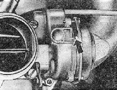
Figure 3.6. Installation marks on the body and cover of the automatic choke.

Figure 3.6. Installation marks on the body and cover of the automatic choke.


Accelerator pump


3. The stroke of the pump piston and its feed are adjusted using the nut on the pump rod.
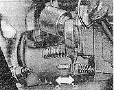
Figure 3.7. Adjusting nut on the accelerator pump rod: a - To reduce the pump flow; b - To increase…

Figure 3.7. Adjusting nut on the accelerator pump rod: a - To reduce the pump flow; b - To increase the pump flow.


4. To determine the pump flow rate, attach a narrow plastic tube to the pump nozzle, the other end of which should be lowered into a measuring cup. The average pump flow is determined for 5 consecutive throttle openings.

5. Once the adjustment is complete, secure the nut on the rod using a dab of paint.

6. Check that the pump directs fuel into the gap between the edge of the throttle valve and the wall of the carburetor body. If necessary, you can bend the end of the sprayer slightly.

Air damper


7. Remove the automatic choke housing cover.

8. Open the throttle valve halfway, close the choke valve by holding it with your finger, and then release the throttle valve.

9. Using a screwdriver, press the diaphragm rod against its stop and measure the gap between the edge of the air damper and the wall of the carburetor body (for this purpose, you can use a drill).

10. If the gap is outside the specified limits, loosen the nut under the cover and adjust the gap using the adjusting screw. When finished, tighten the lock nut again.

Throttle valve


11. Close the choke valve, hold it with your finger, open the throttle valve about halfway and then release it.
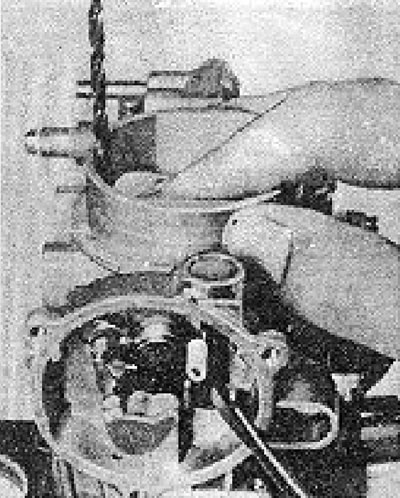
Figure 3.8. Checking the air damper starting gap.

Figure 3.8. Checking the air damper starting gap.


12. Check the gap between the edge of the throttle valve and the wall of the carburetor body (you can use a drill for this chain).

13. If the gap is outside the specified limits, adjust it using the nut on the connecting rod (see Figure 3.10). When finished, secure the nut to the rod using a lock nut.
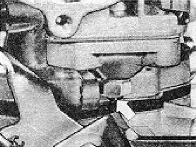
Figure 3.9. Air damper starting clearance adjustment screw and its lock nut (shown by the arrow).
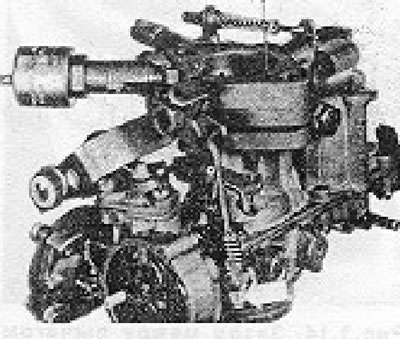
Figure 3.9. Air damper starting clearance adjustment screw and its lock nut (shown by the arrow).


Figure 3.10. Checking the throttle valve starting clearance. The arrow shows the adjusting nut on…

Figure 3.10. Checking the throttle valve starting clearance. The arrow shows the adjusting nut on the connecting rod.


Machine adjustment


14. The following 2 procedures can only be performed after installing the carburetor on the engine and bringing the engine to normal operating temperature

Throttle stop screw


15. This screw is located under a special plug and its adjustment is only necessary after replacing any carburetor parts.
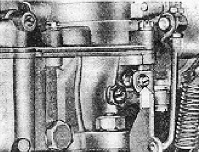
Figure 3.11. Throttle valve stop screw.

Figure 3.11. Throttle valve stop screw.


16. Disconnect the vacuum hose from the carburetor that goes to the distributor and connect a vacuum gauge instead.

17. Start the engine and let it idle.

18. Turn the stop screw so that the vacuum gauge begins to show a vacuum, and then turn it out so that the vacuum drops to zero. Loosen the screw from this position another 1/4 turn.

19. Adjust idle speed and mixture composition (see section 8). Install a new protective cap on the screw.

Carburetor damper and time delay valve (starting with engine No. CH 032 935)


20. With the engine idling, manually (lightly) press the control lever against the adjusting screw.
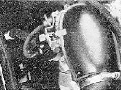
Figure 3.12. Press the carburetor damper control lever (shown by the arrow) to the adjusting screw.

Figure 3.12. Press the carburetor damper control lever (shown by the arrow) to the adjusting screw.


21. Check the tachometer to ensure the engine speed is 1350-1450 rpm. If necessary, adjust the idle speed using the adjusting screw.

The information is posted on this website: VWmanual.ru
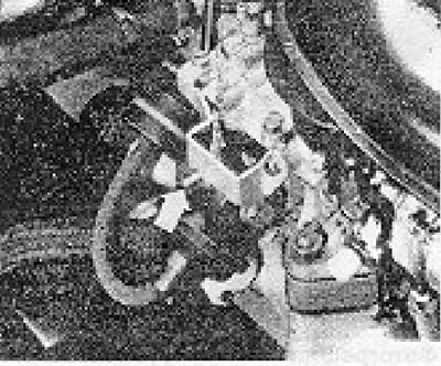
Figure 3.13. Carburetor damper adjusting screw.

Figure 3.13. Carburetor damper adjusting screw.


22. Increase the engine speed to 3000 rpm and again press the control lever on the carburetor damper against the adjusting screw. Reduce engine speed - the control lever should slowly move away from the adjusting screw, and the throttle valve should close completely.

23. If you removed the timing valve that these carburetors are equipped with, when installing it, you should check that the terminal marked in white is connected to the carburetor.

This article is available at russian, bulgarian, belarusian, ukrainian, serbian, croatian, romanian, polish, slovak, hungarian
The text has been checked: Kolesnikov Artem

Share information:

Previous articles
Carburetor — disassembly and assembly
Carburetor — removal and installation
Carburetor — regulation of idle speed and mixture composition
Fuel tank — removal, cleaning and installation
Fuel level sensor — removal and installation
Fuel pump (electric) — removal and installation
Next articles
Throttle Pedal Cable — adjustment
Exhaust Gas Afterburning System — description and maintenance
Manifolds and exhaust system — general information
Fuel system — troubleshooting
Fuel system specification — 2.4l engine
General description — models with a 2.0l engine produced since 1980.


Similar articles from other manuals for VW cars:
Carburetor adjustment Passat B3 (1988-1993)
Carburetor adjustment Golf 1 (1974-1984, petrol)
Seat adjustment Polo 3 (1995-2003)
Removal, installation and adjustment of the multi-function… Touareg 1 (2002-2006)
Damping adjustment key E387 Tiguan 1 (2007-2015)
Knock sensor. Knock adjustment Sharan 1 (1995-2000)
Carburetor adjustment 34 PICT Transporter T3 (1979-1992)
Link to this page in different formats


Visitor comments


No comments yet


How much will 20 + 12 =


Caddy 3 
  • General information
  • User manual
  • Daily care
  • Maintenance
  • Petrol engines 1.4 l
  • Engine repair
  • Cooling and lubrication system
  • Power and exhaust system
  • Petrol engines 1.6 l
  • Engine repair
  • Cooling and lubrication system
  • Power and exhaust system
  • Diesel engines
  • Engine repair
  • Cooling and lubrication system
  • Power and exhaust system
  • Transmission
  • Mechanical gearbox 0AH
  • Mechanical gearbox 0A4
  • Drive shafts
  • Chassis
  • Car suspension
  • Steering
  • Brake system
  • Body and wiring diagrams
  • Interior and exterior
  • Electrical circuits
Beetle 
  • General information
  • Maintenance
  • Power unit
  • Engine repair
  • Cooling and lubrication system
  • Supply system
  • Exhaust system
  • Transmission
  • Clutch
  • Car gearbox
  • Chassis
  • Front suspension
  • Rear suspension
  • Steering
  • Brake system
  • Wheels and tires
  • Body
  • Exterior
  • Electrical equipment
  • Equipment and devices
  • Power devices
  • Electrical circuits
LT 2D 
  • General information
  • User manual
  • Maintenance
  • Power unit
  • Petrol engines 2.3 l
  • Diesel engines 2.5 l
  • Diesel engines 2.8 l
  • Injection system (diesel 2.8 l)
  • Transmission
  • Clutch
  • Manual gearbox
  • Differential
  • Chassis
  • Car suspension
  • Steering system
  • Brake system
  • Body
  • Body elements
  • Heating system
  • Electrical equipment
  • Equipment and devices
  • Electrical circuits
LT 28 
  • General information
  • Maintenance
  • Power unit
  • Petrol engines 2.0L
  • Petrol engines 2.4L
  • Diesel engines
  • Cooling and heating
  • Fuel and exhaust system
  • Ignition system
  • Transmission
  • Clutch
  • Car gearbox
  • Cardan shaft
  • Rear axle
  • Chassis
  • Brake system
  • Car suspension
  • Steering system
  • Body
  • Body elements
  • Doors, locks and windows
  • Electrical equipment
  • Power devices
  • Equipment and devices
  • Electrical circuits
VWmanual.ru © 2016-2026 | Mobile version | News and articles | Sitemap: EN BG BY UA RS HR RO PL SK HU | Write message | Site search
Passat B2 • Passat B3 • Passat B4 • Passat B5 • Passat B6 • Golf 1, diesel • Golf 1, petrol • Golf 2, petrol • Golf 2 • Golf 3 • Golf 4 • Golf 5 • Polo 3 • Polo 4 • Touareg 1 • Tiguan 1 • Sharan 1 • Transporter T3 • Transporter T4 • LT 28 • LT 2D • Beetle • Caddy 3 •
Our website uses cookies to ensure functionality and convenience.