



2. This carburetor is a single barrel, downdraft, manual choke carburetor.
3. The procedure for overhauling and repairing the carburetor remains the same as indicated in chapter 3. Installation and adjustment data are given in the Specifications at the beginning of this Appendix.
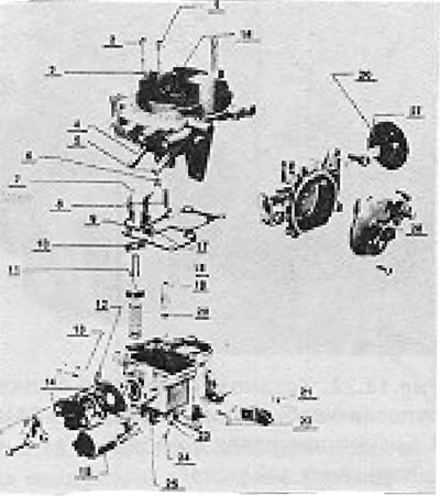
Figure 13.19. Solex 1B1 carburetor disassembled (section 6A): 1-Fuel / air jet idling system; 2 - Auxiliary fuel/air jet; 3 - Mixture enrichment system tube; 4 - Connection point of the fuel supply hose; 5 - Connection point of the return fuel hose; 6 - Main jet; 7 - Float; 8 - Needle valve; 9 - Gasket; 10 - Support ring; 11 - Cup; 12 - Sealing ring; 13 - Quantity screw; 14 - Partial engine load mixture enrichment valve; 15 - Air bypass cut-off valve; 16 - Air damper starting gap regulator; 17 - Axis; 18 - Pump piston; 19 - Spray tube; 20 - Sealing ring; 21 - Adjusting screw; 22 - Air bypass heater; 23 - Sealing ring; 24 - Quality screw; 25 - Connection point for the vacuum ignition regulator tube; 26 - We will follow the air flow descent; 27 - Locking pin; 28 - Choke block cover.
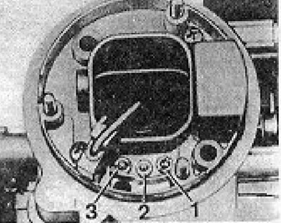
Fig. 13.20. Location of jets in the upper cover of the carburetor (1B1) (section 6A): 1-Fuel / air jet idling system; 2 - Air jet with emulsion tube (cannot be removed); 3 - Auxiliary fuel, air jet.
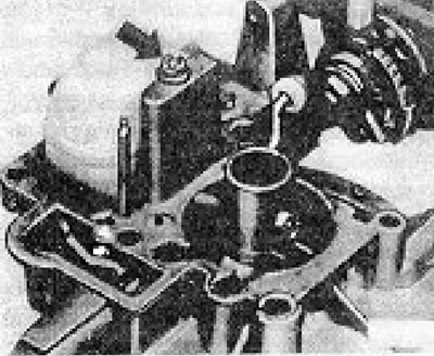
Figure 13.21. Main jet (shown by the arrow) on carburetor 1B1 (section 6A).
Visitor comments