
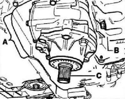
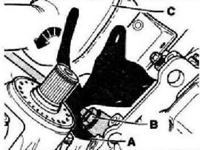
Feed transfer box through opening -A- of subframe without touching engine -B-. The stub shaft -C- must point downwards. Connect the attached planes of the crankcases of the transfer case and the gearbox, if necessary, twisting the semi-axial shaft to align the splines. With the correct alignment of the nodes, the transfer case fits effortlessly against the gearbox.
Instructions: Do not pull the transfer case to the gearbox using the mounting bolts - the transfer case will stand skewed, and one of the mounting ears may break off (lug for fixing hole).
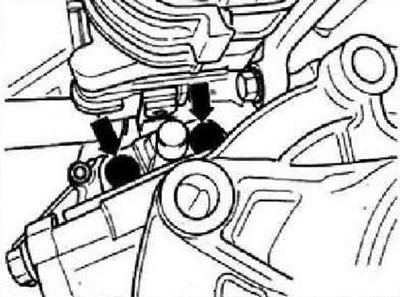
Screw in the top bolts (-arrows-) fasteners of the transfer case to the gearbox and tighten them to a torque of 40 Nm, and then tighten them by 90°.
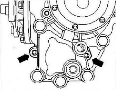
Screw in lower bolts -arrows- for transfer box to gearbox and tighten to 40 Nm, then turn 90°further.
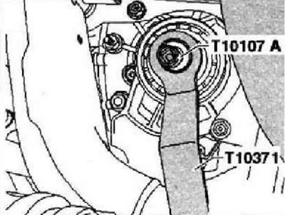
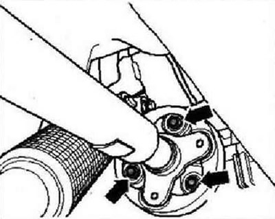
Tighten the screw securing the right semi-axial shaft to 35 Nm.
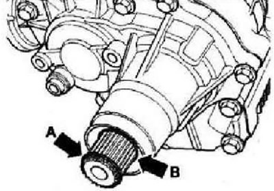
Then install new circlip -arrow A- and new sealing ring -arrow B-.
Install the transfer case mounting bracket. Guide lug -A- behind support -B- for turbocharger. Then turn the bracket to the transfer case (-arrow-); In doing so, raise the particulate filter -C-.
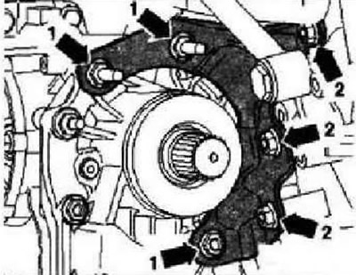
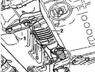
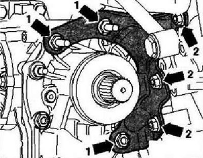
Bolt transfer case bracket to engine and transfer case, following the tightening sequence of bolts -arrows 1- and -arrows 2-. Install the particulate filter.
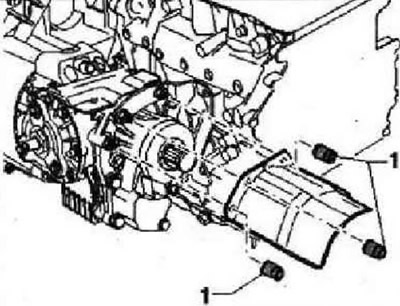
If equipped, install a heat shield for the drive shaft on the transfer case (nuts -1-).
Bolt rear axle drive shaft to transfer case -arrows-. Apply grease -G 000 100- to shaft splines. Install the right drive shaft.
Install lower power unit support, bolts -1- and -2-. Check the oil level in the transfer case.
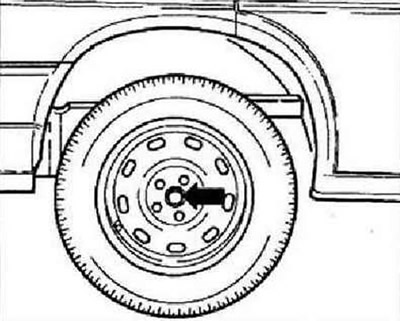
Install soundproof cover. Tighten securing bolt -arrow- for drive shaft.
Tightening torques
| Pos. | Bolt | PC. |
| 1 | М10х45 | 3 |
| 2 | М10х21 | 3 |
The installation of the bracket must be carried out in the following order. Screw in bolts -arrows 1- by hand. Screw in bolts -arrows 2- and tighten to 40 Nm. Tighten bolts -arrows 1- to 40 Nm.
Visitor comments