
Instructions: Replaced, self-locking nuts and bolts. Replace bolts/screws that are tightened by a certain angle. In the course of work, it is necessary to reinstall all cable ties that are removed or cut during dismantling in their original places. Clean input shaft splines and, if using a used clutch disc, also its hub splines, remove any corrosion and apply a very thin layer of spline grease -G 000 100- to the splines. Then, moving the clutch disc along the input shaft, achieve free sliding of its hub. Excess grease must be removed.
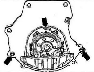
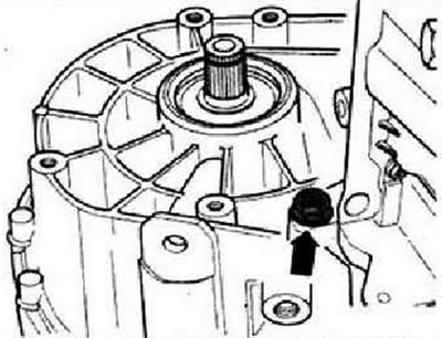
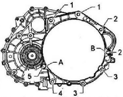
When replacing the gearbox, rearrange the levers for engaging and selecting the gear assembly with the cable mounts to the new unit. All threaded holes into which self-locking bolts/screws have been screwed must be cleaned with a tap to remove the remnants of thread locking agent. Check whether the centering sleeves are inserted into the cylinder block (for the correct alignment of the engine and gearbox). In the absence of centering sleeves, it is difficult to shift gears, the clutch does not work well and noise may occur (gears freely rotating on the shafts make noise). Make sure that the adapter plate is fitted and that the centering sleeves -arrows- are inserted.
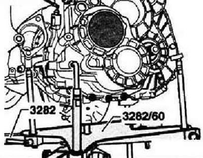
check the clutch release bearing. Replace the worn bearing assembly with the working cylinder. Mounting bracket -3282- is adjustable for gearbox installation work "0А6" using installation template -3282/60-. Attach mounting bracket -3282- to engine and gearbox jack -VAG 1383 A-. Align the tabs of the mounting bracket with the holes in the mounting template. Screw in catches -A- as shown on the setting template. Screw in catch -C- = pin -3282/34-. Place gearbox on engine and gearbox jack -VAG 1383 A-.

Align the setting template parallel to the gearbox. Position engine and transmission jack -VAG 1383 A- under vehicle. the arrow on the setting template indicates the direction of travel of the vehicle.
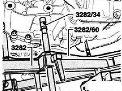
Then screw bolt -3282/34- into the hole for the lower bearing of the power unit on the gearbox. Tilt mounting bracket -3282- to left side of gearbox with spindles.
After that, carefully raise the gearbox without touching the side member.
Instruction: When lifting the gearbox, take care not to damage the pipes and wires.
Use the spindles of the mounting bracket -3282- to move the gearbox into the installation position.
Align the gearbox with the engine and install the gearbox on the centering sleeves.
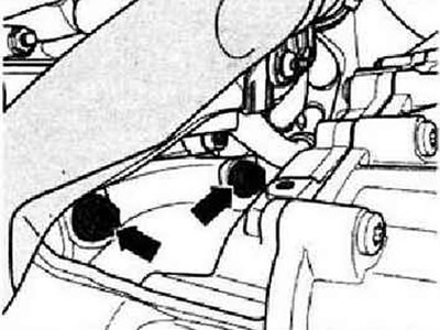
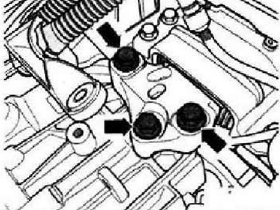
Screw in lower gearbox-to-engine bolts -arrows- and tighten to specified torque. Screw in bolts securing gearbox to engine -arrow- and tighten to specified torque. When the gearbox is bolted to the engine from below, remove the mounting bracket -3282- from the gearbox. Bring power unit into installation position. To do this, raise the power unit so that the gearbox rests completely on the left support of the power unit.
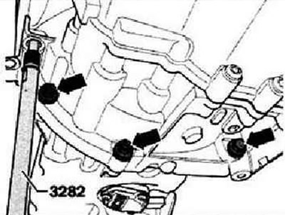
Screw in new bolts -arrows- for left power unit support and tighten to specified torque.
ATTENTION: It is only allowed to detach the traverse -10-222 A- after all bolts securing the power unit support have been tightened to the prescribed torque.
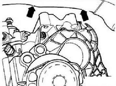
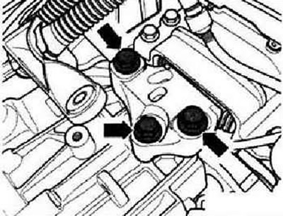
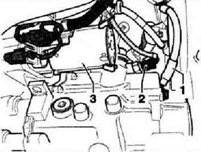
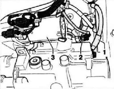
Screw in upper gearbox-to-engine bolts -arrows- and tighten to specified torque. Install starter -3-. Connect connector -2- to reversing light switch -F4-.
Screw ground wire -1- to gearbox.
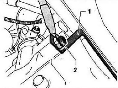
If clip -1- is present, secure ground wire with nut -2-.
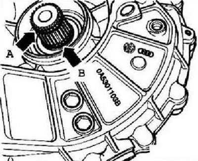
Renew circlip -arrow A- and O-ring -arrow B- on splined shafts. Lubricate splines of drive shafts with grease -G 000 100-. Install drive shafts.
If fitted, install a heat shield for the drive shaft on the engine (bolts -1-), Install the subframe/wishbones, powertrain lower support and steering box.

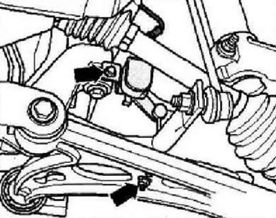
Install lower power unit support, bolts -1- and -2-. Assemble the exhaust system and install the system bracket on the subframe.
If fitted, install front ride height sensor -arrows-.

Install charge air hose -arrow 1- and -arrow 2-. Insert pipe -A- into slave cylinder tee as far as it will go and press in retainer -arrow-.
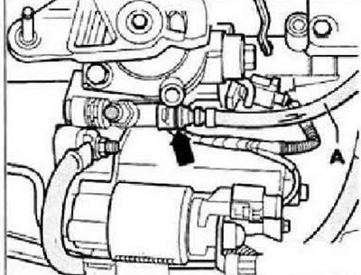
Check that the connection is secure by pulling on the pipeline.
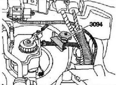
Remove clamp -3094- from hose. After removing clamp -3094- from hose, reshape hose if necessary. Bleed the hydraulic clutch.

Screw in bolts -arrows- for drive cable support bracket on gearbox and tighten to specified torque. Fit selector lever -2- and tighten its securing nut to the specified torque.
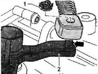
Apply a small amount of grease -G 000 450 02- to the pin -arrow- of the selector lever -2-. Connect the shift cable, use a new lock washer -1- after each removal. Install the gear selector lever assembly with the cable retainer. Adjust gearshift mechanism. Install the battery, bracket and shroud.
Install the air filter housing assembly, if removed. Install the engine cover, if removed. Connect the battery and then carry out the necessary work. Check the oil level in the gearbox. Screw on fender liner for front left wheel housing. Install soundproof cover. Install wheels. On vehicles with front ride height sensor, check headlight adjustment.
Tightening torques
Gearbox to engine
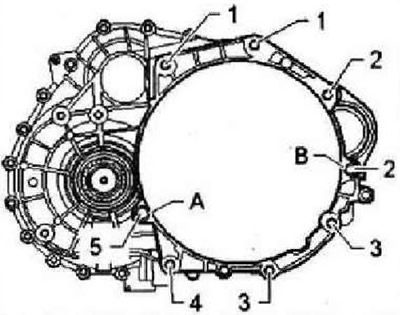
| Pos. | Bolt | PC. | Nm |
| 1 | М12х50 | 2 | in |
| 2 | M12X165 | 2 | 80 |
| 3 | M10x50 | 2 | 40 |
| 4 | M10x68 | 1 | 40 |
| 5 | М12х55 | 1 | 80 |
Pos. -A- and -B-: Centering sleeves.
Gearbox to body
Replace bolts. Bolts -arrows-: 60 Nm and turn 90°further.
Instruction: The power unit must be fixed without tension and distortion. Nut or bolt for attaching earth cable -1- to manual gearbox - 20 Nm.
Visitor comments