



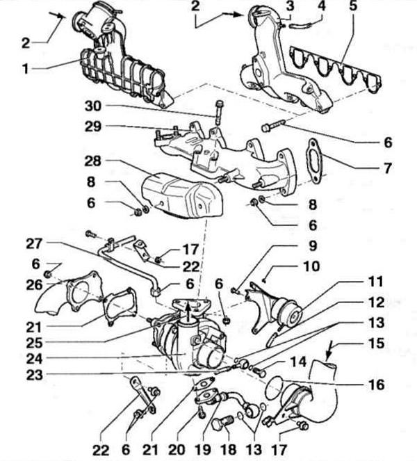
Fig. 6.58 a. Turbocharger with attached elements of AHU, ALE engines:
1 - Intake manifold (aLE engine); 2 - From the intercooler; 3 - Intake manifold (aHU engine); 4 - Tube, black, from the engine control unit; 5, 7, 21 - Gaskets; 6 - Nut; 8 - Washer; 9, 14, 17, 18, 20, 30 - Bolts; 10 - Retaining ring; 11 - Receiver (for boost pressure control valve); 12 - Tube, blue, to the boost pressure control solenoid valve; 13 - Seals; 15 - From the air filter; 16 - Sealing ring; 19 - Oil drain line; 22 - Retainer; 23 - Tube, black, to the boost pressure control solenoid valve; 24 - Turbocharger; 25 - To the intercooler; 26 - Front part of the exhaust pipe; 27 - Oil injection line; 28 - Heat-protective casing; 29 - Exhaust manifold.
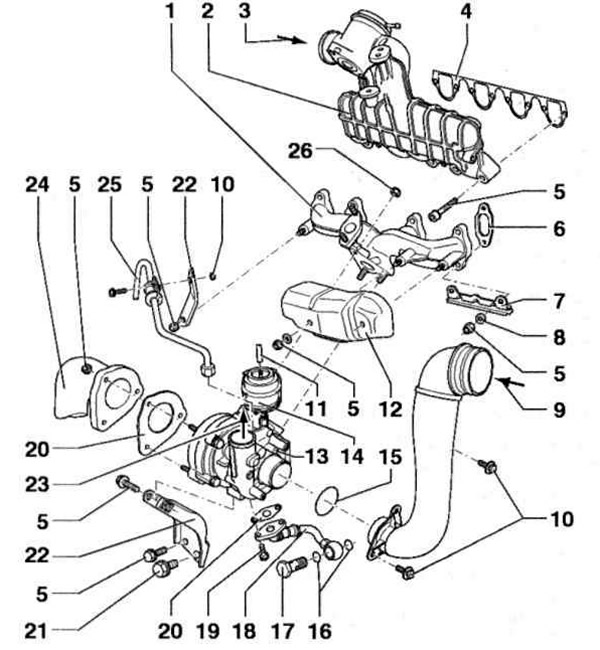
Fig. 6.58 b. Turbocharger with attached elements of the AFN engine:
1 - Exhaust manifold; 2 - Intake manifold with exhaust gas recirculation valve; 3 - From the intercooler; 4, 6, 20 - Gaskets; 5, 10, 17, 19, 21 - Bolts; 7, 22 - Fixators; 8 - Washer; 9 - From the air filter; 11 - Tube to the boost pressure control solenoid valve; 12 - Heat-protective casing; 13 - Turbocharger; 14 - Receiver (for boost pressure control valve); 15 - Sealing ring; 16 - Seals; 18 - Oil drain line; 23 - To the intercooler; 24 - Front part of the exhaust pipe; 25 - Oil pressure line.
[The information is available on the website vwmanual]
Visitor comments