
English Русский
Български
Беларускі
Український
Српски
Hrvatski
Română
Polski
Slovenský
Magyar
  |  Articles  |  Sitemap  |  Contacts  |    |
Car maintenance Ford Car maintenance Hyundai Car maintenance Chevrolet Car maintenance BMW Car maintenance Audi Car maintenance Opel Car maintenance AvtoVAZ
VWmanual.ru


Main   Passat   Golf   Polo   Touareg   Tiguan   Sharan   Transporter   Others  
Polo 3 (1995-2003) Polo 4 (2001-2009)

Exhaust gas recirculation system (VW Polo 3)

  • Main
  • Polo
  • Polo 3
  • Power unit
  • Diesel engines 1.7 and 1.9
  • Exhaust gas recirculation system
            0


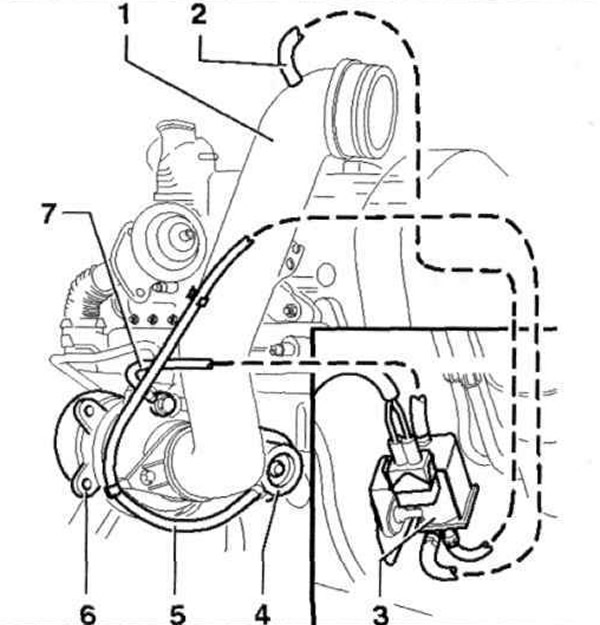
The arrangement of the exhaust gas recirculation system tubes of the AHU and ALE engines is shown in Fig. 6.60 a, and of the AFN engine - in Fig. 6.60 b. The arrangement of the exhaust gas recirculation system elements of the 1Y, AEY, AHB. AKW engines is shown in Fig. 6.61 a, of the AHU engine - in Fig. 6.61 b, and of the AFN and ALE engines - in Fig. 6.61 c.

Fig. 6.60 a. Location of exhaust gas recirculation system tubes for AHU, ALE engines:

Fig. 6.60 a. Location of exhaust gas recirculation system tubes for AHU, ALE engines:
1 - Inlet manifold; 2, 7 - Tubes, black; 3 - Boost pressure control solenoid valve; 4 - Boost pressure control unit; 5 - Tube, blue; 6 - Turbocharger.
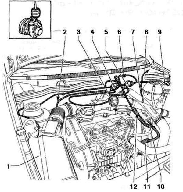

Fig. 6.60 b. Location of the exhaust gas recirculation system tubes of the AFN engine:

Fig. 6.60 b. Location of the exhaust gas recirculation system tubes of the AFN engine:
1 - Air filter; 2 - Boost pressure control unit; 3 - Mechanical exhaust gas recirculation valve; 4 - Exhaust gas recirculation valve; 5 - Boost pressure control solenoid valve; 6, 10 - Bypass valves; 7 - Intake manifold/intercooler vacuum pipe; 8 - To the engine control unit; 9 - To the vacuum tank; 11 - To the vacuum pump; 12 - To the air conditioner.
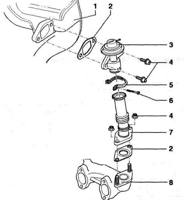


Fig. 6.61 a. Location of elements of the exhaust gas recirculation system of engines 1Y, AEY, ANV,…

Fig. 6.61 a. Location of elements of the exhaust gas recirculation system of engines 1Y, AEY, ANV, AKW:
1 - Intake manifold; 2 - Gasket; 3 - Mechanical exhaust gas recirculation valve; 4 - Nut; 5 - Clamp; 6 - Bolt; 7 - Connecting tube; 8 - Exhaust manifold.
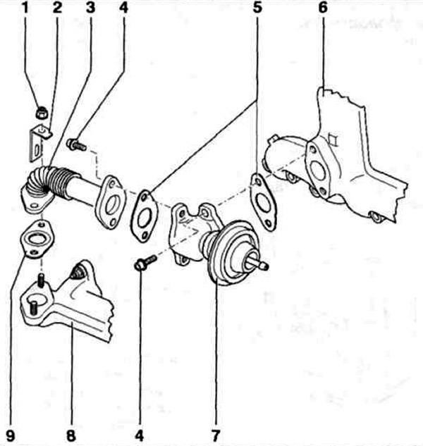

Fig. 6.61 b. Location of the elements of the AHU engine exhaust gas recirculation system:

Fig. 6.61 b. Location of the elements of the AHU engine exhaust gas recirculation system:
1 - Nut; 2 - Bracket; 3 - Connecting tube; 4 - Bolt; 5, 9 - Gaskets; 6 - Intake manifold; 7 - Mechanical exhaust gas recirculation valve; 8 - Exhaust manifold.


The original can be viewed on the portal [VWManual]
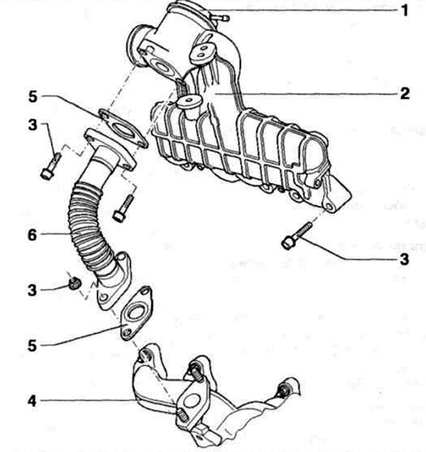
Fig. 6.61 c. Location of elements of the exhaust gas recirculation system of AFN, ALE engines:

Fig. 6.61 c. Location of elements of the exhaust gas recirculation system of AFN, ALE engines:
1 - Exhaust gas recirculation valve; 2 - Intake manifold; 3 - Bolt; 4 - Exhaust manifold; 5 - Gaskets; 6 - Connecting tube.

This article is available at russian, bulgarian, belarusian, ukrainian, serbian, croatian, romanian, polish, slovak, hungarian
The text has been checked: Kolesnikov Artem

Share information:

Previous articles
Intercooler (intermediate cooling of the supercharged air)
Turbocharging a diesel engine
Adjusting the accelerator pedal position sensor (engines AEY, AFN, AHB, AHU, AKW, ALE)
Checking the accelerator pedal position sensor (engines AEY, AFN, AHB, AHU, AKW, ALE)
Accelerator pedal
Fuel filter
Next articles
Checking the components of the exhaust gas recirculation system
Checking the mechanical EGR valve
Diesel fuel injection control system
Self-diagnosis of the injection system
Connecting the VAG 1551 fault code reader
Querying fault memory


Similar articles from other manuals for VW cars:
Exhaust gas recirculation system Passat B6 (2005-2010)
Exhaust system Golf 1 (1974-1984, petrol)
Exhaust system alignment Touareg 1 (2002-2006)
Exhaust gas recirculation systems Tiguan 1 (2007-2015)
Removal and installation of the exhaust system Sharan 1 (1995-2000)
Engine and exhaust system Transporter T4 (1990-2003)
Exhaust gas recirculation (EGR) system Caddy 3 (2003-2010)
Link to this page in different formats


Visitor comments


No comments yet


How much will 41 + 31 =


Polo 4 
  • General information
  • User manual
  • Maintenance
  • Power unit
  • Engine repair
  • Cooling and lubrication system
  • Control system
  • Injection system (diesel)
  • Supply system
  • Exhaust system
  • Chassis
  • Front suspension
  • Rear suspension
  • Steering
  • Wheels and tires
  • Brake system
  • Body
  • Interior
  • Exterior
  • Electrical equipment
  • Equipment and devices
  • Wiper system
  • Lighting system
  • Electrical circuits
Polo 3 
  • General information
  • User manual
  • Maintenance
  • Power unit
  • Petrol engines 1.4 and 1.6
  • Petrol engines 1.4 (V16)
  • Petrol engines 1.6 and 1.8
  • Diesel engines 1.7 and 1.9
  • Diesel engines 1.9 D and TD
  • Transmission
  • Mechanical gearbox 085
  • Mechanical gearbox 020/02K
  • Chassis
  • Front suspension
  • Rear suspension
  • Steering
  • Brake system
  • Body
  • Exterior
  • Interior
  • Electrical equipment
  • Equipment and instruments (until 2000)
  • Equipment and instruments (after 2000)
  • Electrical circuits
  • Wiring diagrams (petrol)
  • Wiring diagrams (diesel)
VWmanual.ru © 2016-2026 | Mobile version | News and articles | Sitemap: EN BG BY UA RS HR RO PL SK HU | Write message | Site search
Passat B2 • Passat B3 • Passat B4 • Passat B5 • Passat B6 • Golf 1, diesel • Golf 1, petrol • Golf 2, petrol • Golf 2 • Golf 3 • Golf 4 • Golf 5 • Polo 3 • Polo 4 • Touareg 1 • Tiguan 1 • Sharan 1 • Transporter T3 • Transporter T4 • LT 28 • LT 2D • Beetle • Caddy 3 •
Our website uses cookies to ensure functionality and convenience.