
1. Remove the clutch pusher from the input shaft.
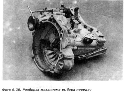
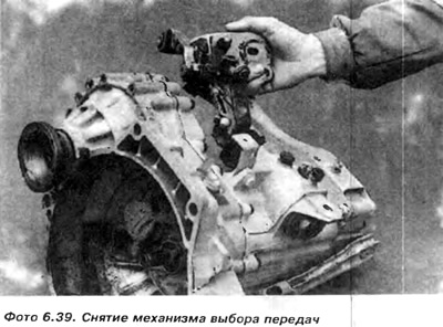
2. Unscrew the bolts and remove the elements of the external gear selection mechanism (photos 6.38 and 6.39).
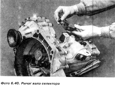
3. Unscrew the nut and remove the selector shaft lever. Please note that the lever enters the shaft in only one position (photo at 6.40).
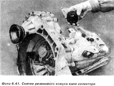
4. Remove the rubber cover of the selector shaft (photo 6.41).
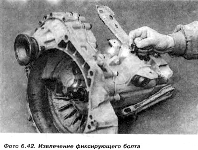
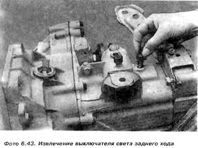
5. Unscrew the bolt fixing (photo 6.42) selector shaft assembly and reverse light switch (photo 6.43).
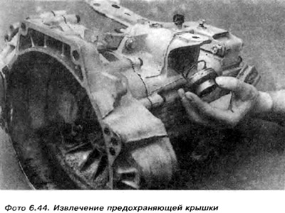
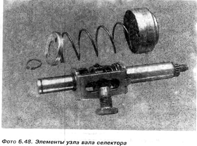
6. Using a spark plug wrench, unscrew the shaft guard and then remove the spring (photo 6.44).
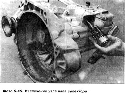
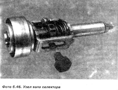
7. Set the selector shaft in neutral position and only then knock the selector shaft assembly out of the housing (photo 6.45).
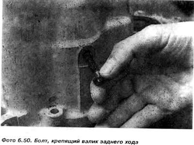
8. Unscrew and remove the bolt securing the reverse gear shaft.
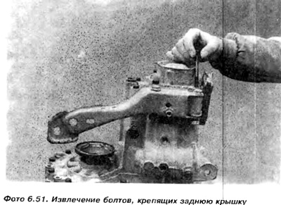
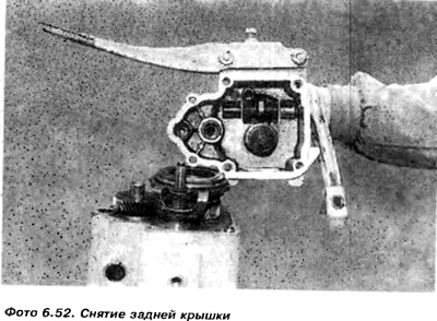
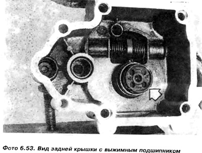
9. Loosen the screws and remove the rear cover from the main body. Remove gasket (photo 6.51 and photo 6.52).
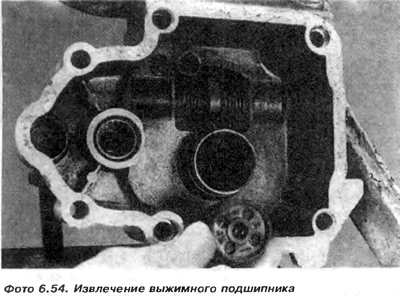
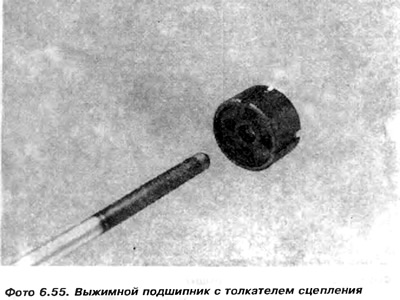
10. Remove the clutch release bearing from the rear cover (photo 6.54).
11. Remove the spring rings from the shaft, switching off the lever 6 (pic. 6.13).
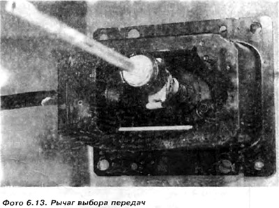
12. Pull the release lever out of the rear housing, paying attention to how the pusher lever 3 and return spring 2 have been installed (pic. 6.13).
Please note that the return spring 1 has different coil diameters (pic. 6.14).
Remember how the ends of the spring are hooked into the body.
Attention: Do not remove slider shaft 1, from the middle of slider 5th speed (photo 6.62).
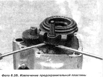
13. Use two screwdrivers to pry up the safety plate of the 5th speed slider (photo 6.56).
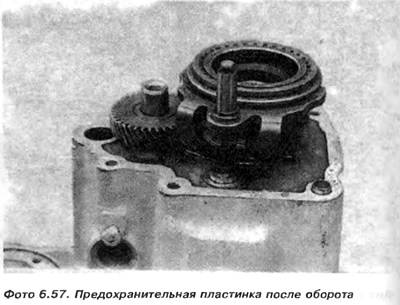
14. Crank (wrap) 90°safety plate (photo 6.57).
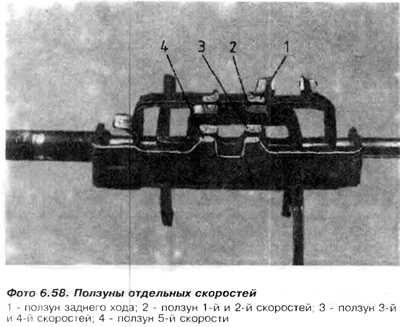
15. Serve fifth and reverse speeds by moving the slider visible in the hole in the selector shaft cover. Individual speed sliders are shown (photo 6.58).
16. Loosen the bolt securing the 5th speed synchronizer assembly using a 12mm slot wrench (photo 6.59 and photo 6.60).
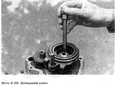
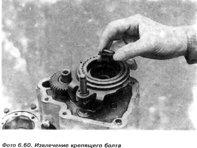
The bolt is screwed in very tightly, so a helper is needed to hold the gearbox.
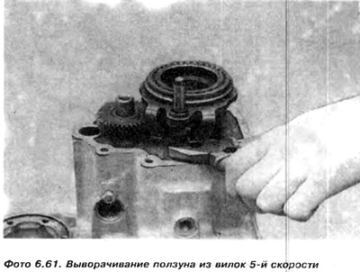
17. Remove the 5th speed slider from the 5th gear forks by turning it counterclockwise. The slider has a left-hand thread. The slider roller still cannot be removed.
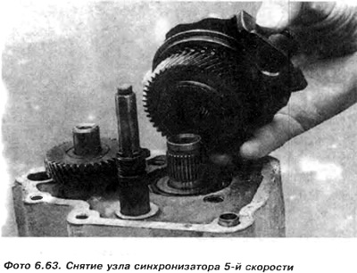
18. Remove the 5th speed synchronizer assembly from the input shaft 21. Pull the 5th speed gear off the output shaft (photo 6.63, 6.66).
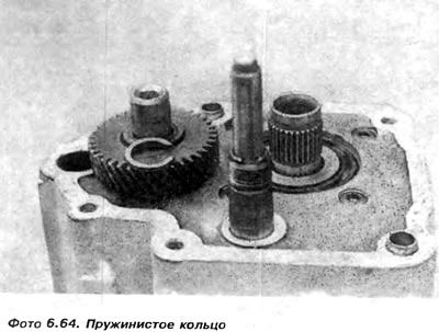
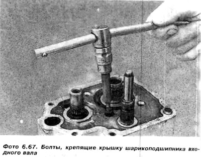
19. Remove the 5th speed gear retaining ring 22. Remove the slotted screws (with slotted sockets) (photo 6.64, photo 6.67).
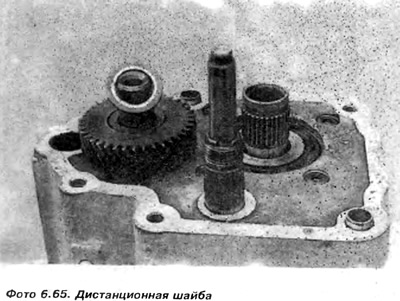
20. Remove spacer (photo 6.65).
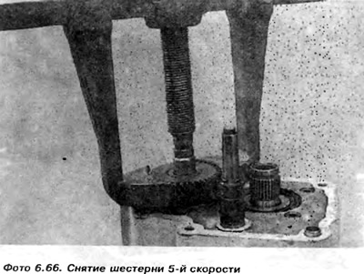
21. Pull the 5th speed gear off the output shaft (photo 6.66).
22. Remove slotted screws (with slotted sockets) (photo 6.67).
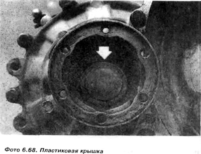
23. Lift the plastic cover and remove it from the middle of the drive flange on the side of the main gear housing (photo 6.68).
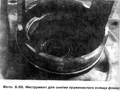
24. Bend the drive flange with a special sleeve and remove the spring ring through the side holes using tongs (photo 6.42).
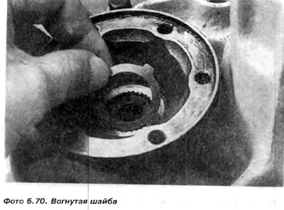
25. Remove the concave washer (photo 6.70)
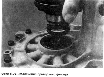
26. Pull out the drive flange (photo 6.71).
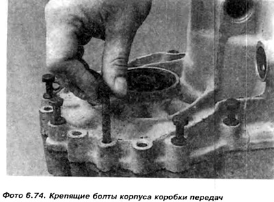
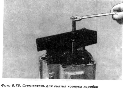
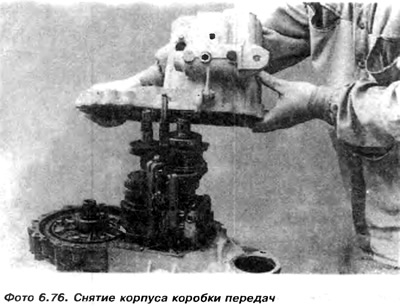
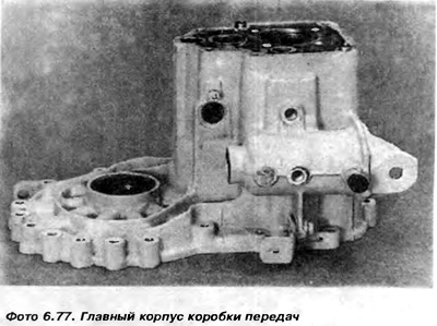
27. Remove the bolts connecting the main body to the clutch housing (photo 6.74).
28. Then you need to use the puller to pull the main body off the input shaft. Retain the spacer located on the outer race of the input shaft ball bearing.
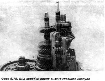
29. Remove the gasket and magnet from the clutch housing.
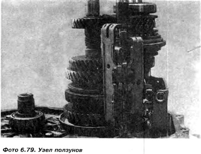
30. Raise the slider shaft and remove the slider assembly with the shaft. Under the slider shaft, in the clutch housing, there is a spring, which must also be removed and stored until assembly.
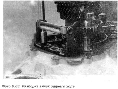
31. Rotate the gearbox and loosen the bolts securing the supports of the reverse gear stacking fork (photo 6.83).
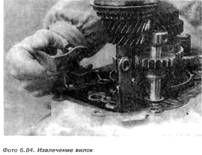
32. Remove the forks from the supports (photo 6.84).
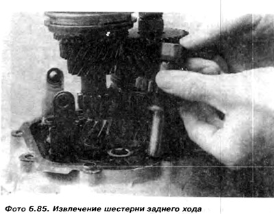
33. Remove the reverse gear along with the shaft (photo 6.85).
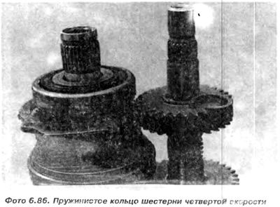
34. Remove the snap ring securing the fourth gear to the output shaft (photo 6.86).
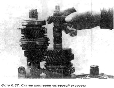
35. Remove the fourth speed gear from the output shaft (photo 6.87).
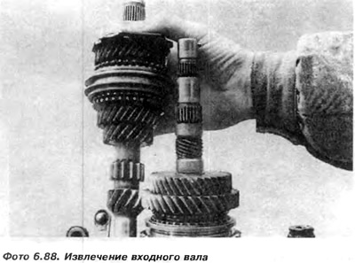
36. Remove the input shaft from the clutch housing. put it aside (photo 6.88). Disassembly information is below.
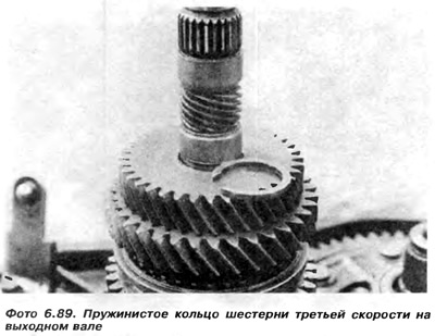
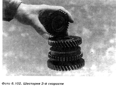
37. Remove the snap ring securing the 3rd gear (photo 6.89).
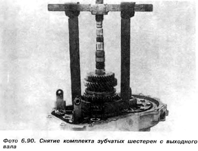
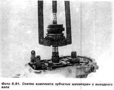
38. Using a special tightener, remove a set of gears from the output shaft (photo 6.90 and photo 6.91). A description of the disassembly of the set of gears is placed below.
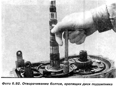
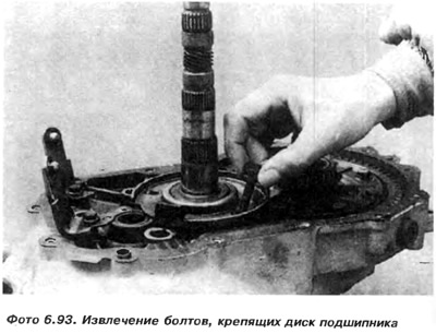
39. Remove the bolts securing the tapered bearing disc (photo 6.92)
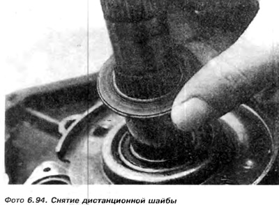
40. Remove the concave washer. Washer with concave side towards tapered bearing (photo 6.94).
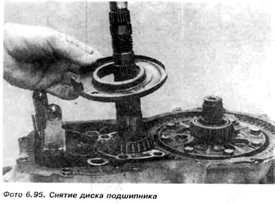
41. Remove the bearing disc (photo 6.95).
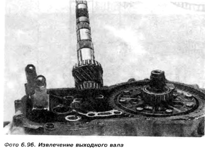
42. Remove the output shaft from the clutch housing (photo 6.96)
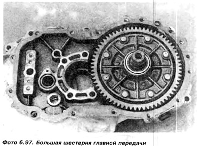
43. Remove the props for the reverse forks (phot 6.97).
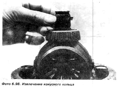
44. Remove the tapered ring from the tapered bearing of the differential mechanism (photo 6.98).
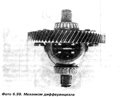
45. Remove the drive flange from the side of the clutch housing and remove the final drive gear with the differential mechanism from the clutch housing (photo 6.99).
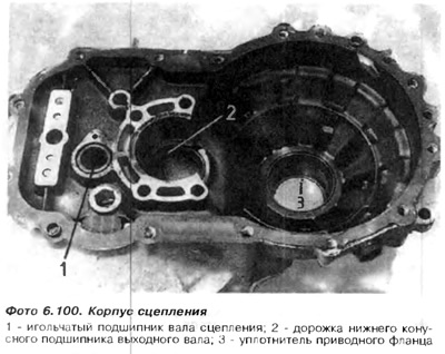
46. If necessary, remove from the clutch housing the needle bearing 1 of the input shaft, the track 2 of the lower bearing of the output shaft, the seal 3 of the differential mechanism (photo 6.100).
Seal 3 is seated in a plastic sleeve, which can be knocked out with a screwdriver. Care must be taken not to damage the casing. After extraction, the sleeve must be replaced with a new one. The new bushing is pressed into place using a suitable tubular mallet.
If necessary, replace the output shaft taper bearings (respectively the node of the differential mechanism), then you should pay attention that the small and large bearings fix the position of the output shaft in relation to the main gear. The appropriate setting is obtained by means of a distance washer which is selected from 16 different thicknesses. If at least one bearing is defective, both must be replaced. During replacement, old bearings break. New bearings should be pressed in and the spacer washer should be replaced with a matching washer under the lower bearing raceway. This operation is quite complex and requires special equipment to preload the shaft and measure the torque required to rotate the new bearing. Also, changing washers under the lower bearing race will affect the spacer on top of the input shaft and the end play measured under the snap ring holding the 3rd speed gear on the output shaft. This means choosing a new spacer and spring washer. There are 6 spring rings, different in thickness. It is recommended that these bearings be replaced by a specialized gearbox repair shop.
47. A set of gears consists of elements shown from 2 to 10 positions (photo 6.15).
43. Disassembly of this kit is not difficult. However, it is necessary to pay attention to the order of disassembly of the elements and their location relative to each other, see the figures below.
49. Disassembly of the input shaft begins with the removal of the ball bearing (photo 6.111)
Note that the bearing is directed by the large inner race diameter towards the 4th speed gear (photo 6.112).
50. Remove the plate that secures the ball bearing to the gearbox housing. Pay attention to which side of the washer is adjacent to the bearing. It is proposed to mark with dots (dotted line) location of the plate on the bearing side (photo 6.113).
51. Remove the 4th speed gear from the needle bearing (photo 6.114).
52. Remove the 4th gear needle bearing from the input shaft (photo 6.115).
53. Remove the 4th speed gear synchronizer ring (photo 6.116).
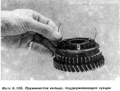
54. Mark with quick-drying paint the side of the movable gear that is on the side of the 3rd speed gear. It doesn't matter if it will be replaced. If the gear is installed on a new one, it is recommended that it work in the same position in which it got used. After removing the movable gear is assembled and secure for assembly crackers.
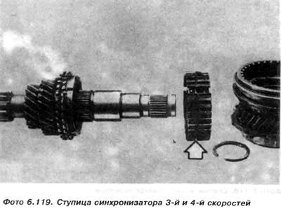
55. The synchronizer hub is fixed to the shaft with a spring ring, which must be removed before pulling the hub off the splines (photo 6.118).
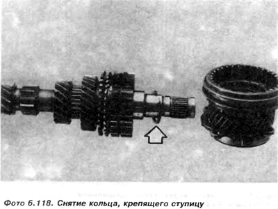
56. Remove the hub from the splines, paying attention to how it faces the 3rd speed gear. If there are difficulties in removing the hub from the splines, it is necessary to remove it together with the 3rd speed gear, catching the tensioner shoulders on this gear.
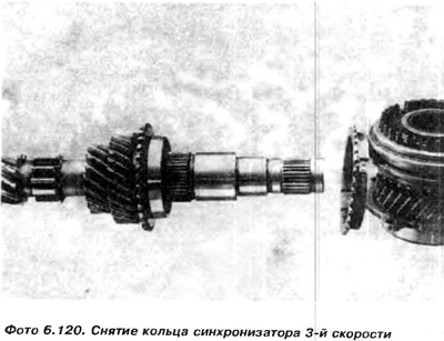
57. Remove the 3rd speed synchronizer ring (photo 6.120).
58. Remove 3rd speed gear (photo 6.121)
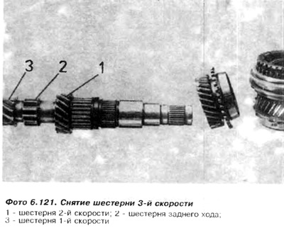
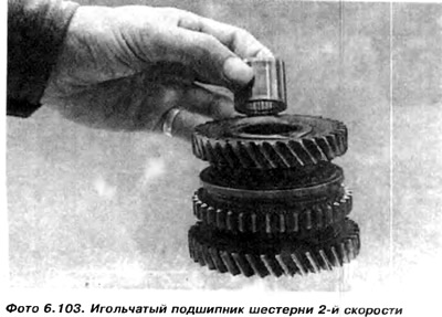
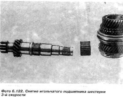
59. Remove the 3rd speed gear needle bearing. Further on the input shaft are gears with notches for 2nd speed, reverse and 1st speed (photo 6.122).
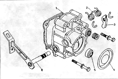
Pic. 6.13. Rear box cover 020, 5-speed
1 - back cover of the box; 2 - return spring; 3 - pusher lever; 4 - back cover; 5 - release bearing; 6 - roller of the switching lever.
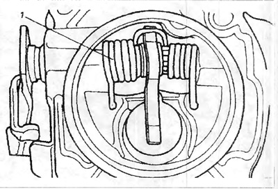
Pic. 6.14. Release lever return spring
1 - return spring of the switching lever.
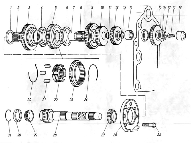
Pic. 6.15. Box output shaft 020 - 5 speed
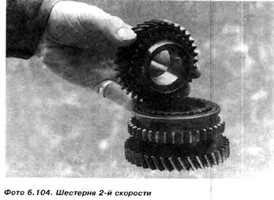
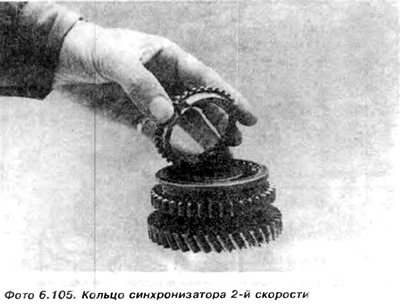
1 concave washer; 2 - 1st gear needle bearing; 3 - 1st gear gear; 4 - synchronizer ring; 5 - synchronizer unit of the 1st and 2nd speeds; 6 - synchronizer ring; 7 - track of a needle bearing; 8 - needle bearing; 9 - gear wheel of the 2nd speed; 10 - 3rd gear gear; 11 - spring ring; 12 - gear wheel of the 4th speed; 13 - spring ring; 14 - screw securing the needle bearing in the box body; 15 - needle bearing; 20 - a ring supporting crackers; 21 - crackers; 22 - synchronizer hub; 23 - movable gear with reverse gear; 24 - a ring supporting crackers, 25 - a bolt securing the bearing disc; 26 - bearing disk; 27 - conical bearing; 28 - output shaft; 29 - lower conical bearing; 30 - track of the lower bearing; 31 spacer for the lower bearing race.

Visitor comments