
17. Take out the gear wheel of the 1st speed of the 12-needle bearing 11.
18. Remove the 1st speed synchronizer ring 10.
19 Remove the support washer (if available), and then, using pliers, remove the spring ring 9 from the synchronizer assembly of the 1st and 2nd speeds. During installation, a new safety spring ring must be installed.
20. With the puller attached below the 2nd speed cogwheel, pull out the cogwheel along with the 1st and 2nd speed synchronizer assembly. After removing, disassemble the assembly into parts and remove the 2nd speed synchronizer ring 7.
21. Remove the 2nd speed gear needle bearing 5.
22. Clean the elements in kerosene and check them for wear. Check gear teeth (releases) and needles. If necessary, replace the elements with new ones. If the gears of the 3rd 4, and 4th speeds 3 require replacement, it must be done on a press. New gears must be heated to 128°C before installation. It should be noted that the landings of both toothed gears are adjacent. The pinion on the output shaft and the large final drive gear do not fit together, so if necessary, the output shaft can be replaced without having to replace the large gear. In this case, it is necessary to check and, if necessary, adjust the longitudinal clearance of the output shaft.
When installing a new output shaft, check the number of teeth on the small gear against the old shaft. The output shaft on the seating surface of the 4th and 3rd speed gears has channels that serve as a day for identification.
For transmission
4,27 — (64:15) shaft without channel
3,88 — (62:16) shaft with one channel
4,05 — (65:16) shaft with three channels.
23. Check the synchronizer rings and synchronizer assemblies.
Installation
24. Installation should begin by placing the 2nd speed pinion needle bearing on the input shaft. Lubricate it with gearbox oil.
25. Install 2nd speed gear 6.
26. Install the 2nd speed synchronizer ring into the 1st and 2nd speed synchronizer assembly so that the 2nd synchronizer crackers are in the cutouts of the ring.
27. Press the synchronizer assembly onto the splines of the shaft after installing the synchronizer assembly, the groove of the forks of the movable gear 8 should be on the side of the 1st speed gear.
28. Install a new spring ring 9 in the groove of the shaft, and then the support washer (if available).
29. Install the 1st speed synchronizer ring into the 1st and 2nd speed synchronizer assembly so that the synchronizer crackers are in the cutouts of the ring.
30. Install the needle bearing 11 of the 1st speed gear on the shaft and lubricate it with gearbox oil, and then install the 1st gear 12.
31. Install support washer 13 and new circlip 14, making sure it is properly seated in the groove.
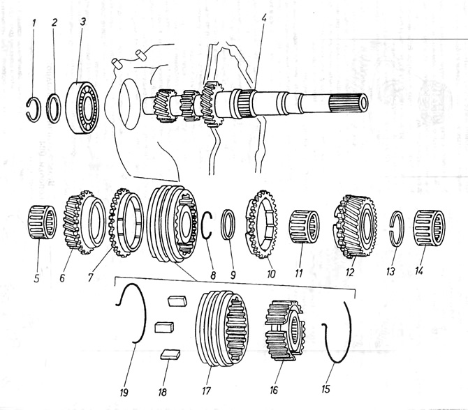
Pic. 6.5. Gearbox input shaft 084
1 - spring ring; 2 - remote washer; 3 - ball bearing; 4 - input shaft; 5 - needle bearing; 6 - gear wheel of the 3rd speed; 7 - synchronizer ring of the 3rd speed; 8 - spring ring; 9 - remote washer; 10 - 4th speed synchronizer ring; 11 - needle bearing; 12 - gear wheel of the 4th speed; 13 - spring ring; 14 - needle bearing; 15 - a ring supporting crackers; 16 - synchronizer hub; 17 - synchronizer housing; 18- synchronizer crackers; 19 - a ring supporting crackers.
Visitor comments