
English Русский
Български
Беларускі
Український
Српски
Hrvatski
Română
Polski
Slovenský
Magyar
  |  Articles  |  Sitemap  |  Contacts  |    |
Car maintenance Ford Car maintenance Hyundai Car maintenance Chevrolet Car maintenance BMW Car maintenance Audi Car maintenance Opel Car maintenance AvtoVAZ
VWmanual.ru


Main   Passat   Golf   Polo   Touareg   Tiguan   Sharan   Transporter   Others  
Golf 1 (1974-1984, diesel) Golf 1 (1974-1984, petrol) Golf 2 (1984-1993, petrol) Golf 2 (1984-1993) Golf 3 (1991-1997) Golf 4 (1997-2004) Golf 5 (2003-2008)

Disassembly and repair of gearbox 084 (VW Golf 2)

  • Main
  • Golf
  • Golf 2
  • Transmission
  • Car gearbox
  • Disassembly and repair of gearbox 084
            0


1. Unscrew the oil drain plug with a hex key and drain the oil into a container. Screw the plug back in.

2. Remove the clutch release bearing and shaft.

3. Unscrew and remove the reverse light switch.

4. Temporarily screw two bolts into each drive flange. While holding the flanges in place one by one with a rod, unscrew the fastening bolts 1 (figure 6.2)
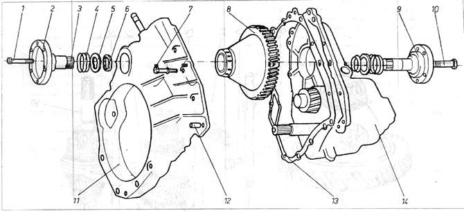
Figure 6.2. Gearbox - 084

1 - fastening bolt; 2 - right drive flange; 3 - vilovurist on the drive flange; 4 - spring; 5 - support washer; 6 - cone ring; 7 bolt securing the clutch housing; 8 - main gear with differential mechanism; 9 - left drive flange; 10 - fastening bolt; 11 clutch housing; 12 - fixing pin; 13 - gasket; 14 - gearbox housing.


Label each flange (right and left), then remove them from the main gear. Drive flanges of different lengths (figure 6.1).
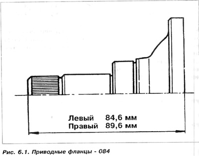
Label each flange (right and left), then remove them from the main gear. Drive flanges of different…


Remove spring 4, support washer 5 and conical ring 6 from the seat of drive flange 2 on the main gear housing and keep them together with the corresponding drive flanges (Fig. 6.2).


5. The drive flange seals can be removed and replaced with new ones if necessary, either immediately or later, after removing the differential mechanism.

This operation can also be performed with the gearbox installed after removing the drive flanges. It should be noted that the right and left seals are different sizes.

6. Loosen and remove the bolts connecting the clutch housing to the main housing. Make sure that all bolts are removed from the clutch housing.

7. Support the gearbox with the clutch housing on top, then use a wooden mallet to separate the clutch housing from the main housing, then set it aside.

8. Remove the magnet that collects sawdust from the groove on the gearbox housing.

9. Remove the differential mechanism from the gearbox.

10. Support the main gearbox housing with the rear cover facing up.

11. Loosen and remove the bolts and the rear bearing cover (photo 6.1). Mark the distance washers of the input and output shaft bearings and then remove them. There is no need to replace the distance washers, as then you will need to adjust the longitudinal clearances of the shafts during installation. Remove the gasket.
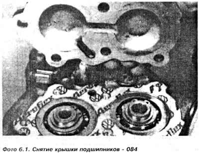
11. Loosen and remove the bolts and the rear bearing cover (photo 6.1). Mark the distance washers…


12. Using pliers, remove the spring retaining ring from the entrance hall, and then remove the small spacer washer (photo 6.2)
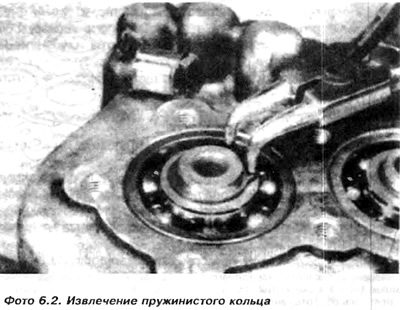

12. Using pliers, remove the spring retaining ring from the entrance hall, and then remove the…


13. Check whether the selector shaft is in a free position, and then use a hex key to unscrew the locking rod together with the bushing washers, springs and locking studs 21 (figure 6.3)

(The original information is posted on the resource vwmanual)
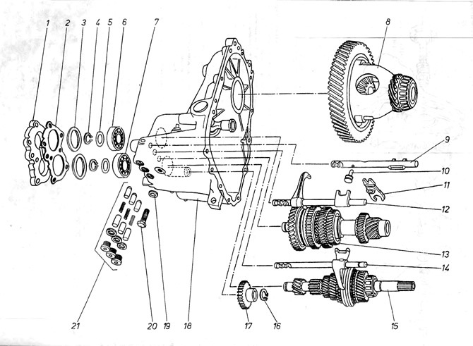
Figure 6.3. Gearbox - 084

1 - rear bearing cover; 2 - gasket; 3 - spacer washers; 4 - spring rings; 5 - spacer washers; 6 - output shaft ball bearing; 7 - Input shaft ball bearing; 8 - differential mechanism; 9 - reverse gear fork slider; 10 - reverse gear pinion fork; 11 - reverse gear forks; 12 - 1st and 2nd speed fork slider; 13 - output roller; 14 - 3rd and 4th speed fork slider; 15 - input roller; 16 - spring ring; 17 - reverse gear; 18 - gearbox housing; 19 - washer; 20 - bolt (axis of rotation) reverse gear fork; 21 - a unit of blocking elements against simultaneous activation of two speeds.


14. Unscrew the 20 bolt with a Phillips-head screwdriver, the reverse gear fork. This bolt is located next to the locking rod holes. The bolt is very tightly clamped, so you will need an impact screwdriver or chisel to remove the bolt.

15. Turn the gearbox housing and remove the slider of the forks of the reverse gear 9 and fork 11. The forks have cutouts at the ends into which the kingpin 10 of the slider 9 fits on one side and the reverse gear 17 on the other side.

16. Then it is necessary to remove the shafts, input 15 and output 43. You can remove two shafts, simultaneously knocking them out through ball bearings 6 and 7.

17. To remove the shafts separately, it is necessary to prepare a special support plate and screw it to the housing so as to make the input shaft immobile (figure 6.4). Place a hex nut M 16 between the shaft lever and the gearbox housing to lock the shaft.
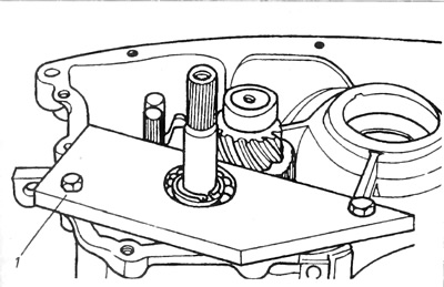
Figure 6.4. Fixing plate (input shaft)

1 - fixing plate.


18. Support the gearbox with the ball bearings upwards, and then use a special puller to remove the input shaft bearing from the housing.

19. Remove the special support plate.

20. Using an M16 nut or a piece of wire, hold the selector shaft by bending the spring.

21. Move the input shaft away from the output shaft, and then remove it together with the slider and the 3rd and 4th speed forks from the gearbox. Slightly lift the reverse gear pinion so that the 1st speed gear pinion of the input shaft can pass.

22. Remove the M16 nut or piece of wire used to lock the selector shaft.

23. Using pliers, remove the spring retaining ring from the end of the output shaft and the small spacer washer (photo 6.2).

24. Using a puller, push the output shaft out of the end bearing and simultaneously remove the slider and 1st and 2nd speed forks and the reverse gear pinion. Make sure that the shaft and reverse gear pinion do not jam.

25. Remove the locking rod 21 from the gearbox housing (if there are any left).

26. Using a soft metal punch, knock the input shaft bearing out of the gearbox housing. Mark the input and output shaft bearings.

This article is available at russian, bulgarian, belarusian, ukrainian, serbian, croatian, romanian, polish, slovak, hungarian
The text has been checked: Semenova Anna

Share information:

Previous articles
Removal the gearbox 084
Frequency of inspection of the gearbox
General characteristics of a manual gearbox
Technical data
Next articles
Clutch housing — repair
Gearbox housing — repair
Input shaft of box 084
Output shaft of box 084
Synchronizers — box 084
Differential mechanism — box 084


Similar articles from other manuals for VW cars:
Gearbox repair Passat B5 (1996-2005)
Disassembly and assembly of the gearbox Polo 3 (1995-2003)
On-board tool, spare wheel, tire repair kit, jack Touareg 1 (2002-2006)
Ignition system repair Tiguan 1 (2007-2015)
General recommendations for car repair Sharan 1 (1995-2000)
Gearbox and wheel drive Transporter T4 (1990-2003)
Valve mechanism repair Caddy 3 (2003-2010)
Link to this page in different formats


Visitor comments


No comments yet


How much will 37 + 18 =


Golf 5 
  • General information
  • User manual
  • Maintenance
  • Troubleshooting
  • Power unit
  • Engine repair
  • Cooling and ventilation system
  • Fuel system
  • Ignition system
  • Transmission
  • Clutch
  • Mechanical gearbox
  • Automatic gearbox
  • Chassis
  • Brake system
  • Car suspension
  • Steering
  • Body
  • Interior (internal elements)
  • Exterior (external elements)
  • Doors and covers
  • Electrical equipment
  • Power devices
  • Washers and wipers
  • Lighting and appliances
  • Electrical circuits
Golf 4 
  • General information
  • User manual
  • Weekly checks
  • Maintenance
  • Power unit
  • Petrol engines
  • Diesel engines
  • Cooling system
  • Fuel system (petrol)
  • Control system (petrol)
  • Fuel system (diesel)
  • Exhaust system
  • Transmission
  • Clutch
  • Car gearbox
  • Drive shafts
  • Chassis
  • Car suspension
  • Steering
  • Wheels and tires
  • Brake system
  • Body
  • Exterior (external elements)
  • Interior (internal elements)
  • Ventilation and heating
  • Car doors and sunroof
  • Washers and glass cleaners
  • Electrical equipment
  • Power devices
  • Lighting and appliances
  • Electrical circuits
Golf 3 
  • Petrol engine
  • Engine repair
  • Lubrication system
  • Cooling system
  • Ignition system
  • Diesel engine
  • Engine repair
  • Diesel injection system
  • Pre-glow system
  • Transmission
  • Clutch
  • Gearbox and drive shafts
  • Chassis
  • Steering
  • Wheels and suspension
  • Brake system
  • Electrical equipment
  • Lighting and appliances
  • Electrical circuits
Golf 2 
  • General information
  • Introduction to guide
  • User manual
  • Petrol engines 1.3 l
  • Engine repair
  • Lubrication system
  • Cooling system
  • Carburetors
  • Supply system
  • Ignition system
  • Petrol engines 1.6/1.8 l
  • Engine repair
  • Supply system
  • Ignition system
  • Diesel engines
  • Engine repair
  • Lubrication system
  • Cooling system
  • Power and exhaust system
  • Transmission
  • Clutch
  • 4-speed gearbox 084
  • 5-speed gearbox 085
  • 4-speed gearbox 020/4R
  • 5-speed gearbox 020/4T
  • Automatic gearbox
  • Drive shafts
  • Chassis
  • Steering
  • Car suspension
  • Brake system
  • Body
  • Body elements
  • Doors, locks and windows
  • Electrical equipment
  • Equipment and devices
  • Power devices
Golf 2 (petrol) 
  • General information
  • Characteristics
  • Car care
  • Maintenance
  • Power unit
  • Engine repair
  • Engine 1.05/1.30
  • Engine 1.60/1.80
  • Cooling and lubrication system
  • Power and exhaust system
  • Transmission
  • Clutch
  • Car gearbox
  • Drive shafts
  • Chassis
  • Brake system
  • Steering
  • Suspension
  • Body
  • Body and equipment
  • Electrical equipment
  • Lighting and appliances
  • Electrical circuits
Golf 1 (petrol) 
  • General information
  • Characteristics
  • User manual
  • Maintenance
  • Power unit
  • Engine adjustment
  • Engine 1.1/1.3
  • Engine 1.5/1.6/1.8
  • Engine electrical equipment
  • Cooling system
  • Fuel system
  • Transmission
  • Clutch and manual gearbox
  • Automatic gearbox
  • Chassis
  • Steering
  • Front suspension
  • Rear suspension
  • Brake system
  • Electrical equipment
  • Lighting and appliances
  • Electrical circuits
  • Body
  • Body and equipment
  • Optional equipment
Golf 1 (diesel) 
  • General information
  • Specifications
  • Maintenance
  • Power unit
  • Engine repair
  • Exhaust and turbocharger
  • Cooling system
  • Fuel system
  • Fuel injection system
  • Transmission
  • Clutch and drive shafts
  • Car gearbox
  • Chassis
  • Suspension and wheels
  • Steering
  • Brake system
  • Wheels and tires
  • Body
  • Heating and ventilation
  • Exterior (external elements)
  • Interior (internal elements)
  • Doors and windows
  • Electrical equipment
  • Equipment and devices
  • Lighting system
  • Power devices
  • Electrical circuits
VWmanual.ru © 2016-2026 | Mobile version | News and articles | Sitemap: EN BG BY UA RS HR RO PL SK HU | Write message | Site search
Passat B2 • Passat B3 • Passat B4 • Passat B5 • Passat B6 • Golf 1, diesel • Golf 1, petrol • Golf 2, petrol • Golf 2 • Golf 3 • Golf 4 • Golf 5 • Polo 3 • Polo 4 • Touareg 1 • Tiguan 1 • Sharan 1 • Transporter T3 • Transporter T4 • LT 28 • LT 2D • Beetle • Caddy 3 •
Our website uses cookies to ensure functionality and convenience.