
Elements should lie on clean paper or foil.
1. Using a metal tube, drive the output shaft bearing into the gearbox housing with the closed side of the bearing facing into the gearbox.
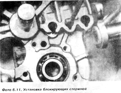
2. Lubricate the locking rods 21 and insert them into the body (pic. 6.3 and photo 6.11).
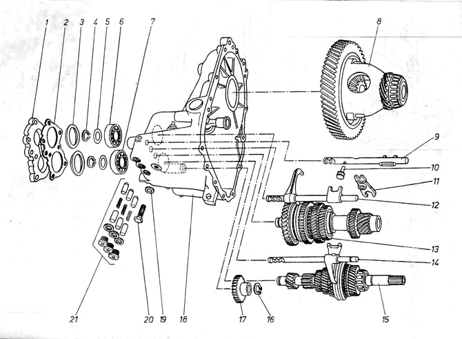
Pic. 6.3. Gearbox - 084
1 - rear bearing cover; 2 - gasket; 3 - spacers; 4 - springy rings; 5 - spacers; 6 - ball bearing of the output shaft; 7 - input shaft ball bearing; 8 - differential mechanism; 9 - slider of reverse gear forks; 10 - pin of the forks of the reverse gear; 11 - reverse gear forks; 12 - slider forks of the 1st and 2nd speed; 13 - output roller; 14 - slider forks of the 3rd and 4th speeds; 15 - input roller; 16 - spring ring; 17 - reverse gear; 18 - gearbox housing; 19 - washer; 20 - bolt (rotation axis) reverse gear forks; 21 - a node of blocking elements against the simultaneous inclusion of two speeds.
You can use a magnetized screwdriver for this if necessary.
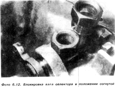
3. Move the selector shaft forward by bending the spring and the M16 nut or block the selector shaft in the appropriate position with a piece of wire (photo 6.12).
4. Install the slider with the forks of the 1st and 2nd speeds 12 into the groove of the movable synchronizer gear on the output shaft 13 (pic. 6.3).
5. Place the reverse gear 17 on its shaft, lift and hold them in this position with a piece of wire.
6. Install the output shaft and slider in the gearbox housing, and at the same time lower the reverse gear behind the first gear.
7. After the final installation of the output shaft in its bearing, check whether the forks of the slider are in a free position, and whether the reverse gear can move freely.
8. If a new gearbox housing, bearing or output shaft is installed, new bearing spacers must be identified and installed.
A) Install the spring ring 17 and use a feeler gauge to measure the gap between the spring ring and the inner race of the ball bearing 15 (pic. 6.6).
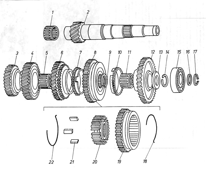
Pic. 6.6. Output shaft 084
1 - needle bearing; 2 - output shaft; 3 - gear wheel of the 4th speed; 4 - gear wheel of the 3rd speed; 5 - needle bearing of the 2nd speed gear; 6 - gear wheel of the second speed; 7 - synchronizer ring; 8 - synchronizer node; 9 - spring ring; 10-ring synchronizer; 11 - needle bearing; 12 - gear wheel of the 1st speed; 13 - remote washer; 14 - spring ring; 15 ball bearing; 16 - remote washer; 17 - spring ring; 18 - ring supporting crackers; 19 - movable gear with reverse gear; 20 - synchronizer hub; 21 - synchronizer crackers; 22 - a ring supporting crackers.
b) Select a small distance washer 16 such that the gap is 0-0.05 mm.
V) Put the washer on the shaft and fasten the spring ring.
G) Using a dial gauge or feeler gauge, measure the distance C between the surface of the gearbox housing (without gasket) and the outer race of the ball bearing 15 (pic. 6.6).
Add 0.27 to 0.31 mm to gap size C to get the thickness of the large spacer to be put on the outer track. When sizing a large spacer, make sure the bearing is fully seated (is sitting) in the housing, and if a temporary sensor is used, it must have a zero reading with 2 mm pre-stretch.
9. Place the slider with the 3rd and 4th speed forks 14 in the groove of the movable synchronizer gear on the input shaft.
10. Install the input shaft and slider with forks into the gearbox housing so that the gears engage the gears on the output shaft.
Attention: Raise the reverse gear slightly so that the first gear of the input shaft can pass through.
11. Support the output shaft with a special plate. described in point 4, and then remove the wire from the reverse gear.
12. Drive input shaft bearing 7 using a metal tube into the gearbox housing and onto the shaft. The closed side of the bearing must face the inside of the gearbox.
13. According to the description of paragraph 8.8, determine and put on the small and large distance washers on the end of the input shaft.
14. Remove the special plate from the input shaft (fig 6.4).
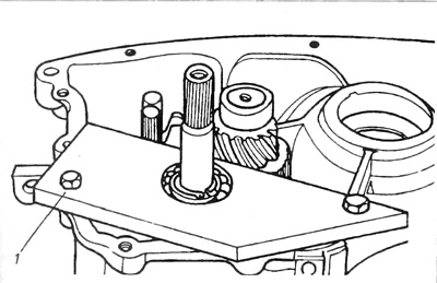
Pic. 6.4. Fixing plate (input shaft)
1 - fixing plate.
15. Remove the M16 nut or wire blocking the selector shaft.
16. Place the forks of the reverse gear 11 on the reverse slider 9, then insert the forks and the slider into the housing and gear the forks with the reverse gear. It will be necessary to slightly raise the gears.
17. Install the reverse gear forks approximately 200 mm from the 1st and 2nd gear slider. Make sure that the axis of rotation on the slider 9 is on the same level with the hole in the forks (pic. 6.3).
18. Install the washer and screw in the socket head screw 20, and then tighten. Check if the gap between the forks 11 and the slider 9 is 1.3-2.8 mm, see figure 6.7.
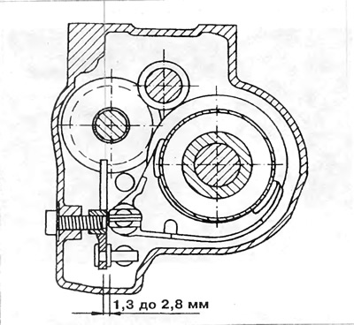
Pic. 6.7. Gap between forks and slider
19. Install the locking rods, springs and bushings into the body holes, and then the plugs with washers. Press the plugs with a hex wrench (pic. 6.8).
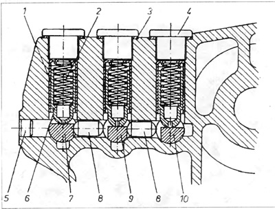
Pic. 6.8. Blocking mechanism for simultaneous engagement of two gears
1 - gearbox housing; 2 - spring; 3 - washer; 4 - threaded plug; 5 - plug; 6 - blocking rod; 7 - reverse slider; 8 - locking plug; 9 - slider 1st and 2nd gear; 10 - 3rd and 4th gear slider.
20. Move the selector shaft lever and check if the gears are easily engaged. It is also necessary to check whether it is possible to advance adjacent sliders simultaneously.
21. Place large shims on the ball bearings of the input and output shafts, put on the back cover 1 of the gearbox along with a new gasket. Lubricate the threads of the bolts with a liquid preservative. Insert the bolts and tighten them with the appropriate torque crosswise (pic. 6.3).
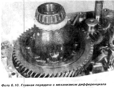
22. Unscrew the gearbox and install the differential mechanism (photo 6.10).
23. Clean the mating surfaces of the clutch housing and main housing. Install a new gasket if previously installed, otherwise sealing paste must be applied to these surfaces
24. Place the magnet in the gap of the gearbox housing.
25. Check that the sliders are in the free position, and then push the clutch housing onto the main gearbox housing, checking if the gear selection lever of the clutch housing is geared with the selector shaft center lever.
26. Drive in the fixing studs, and then install the bolts and clamp them evenly crosswise with the appropriate torque.
27. Insert the drive flanges into the differential mechanism together with the V-ring, thrust washer and spring. Insert the bolts and tighten them to the appropriate torque. Hold the flanges motionless with a rod placed between two bolts inserted into adjacent holes in the drive flange. Please note that the right and left flanges are different (see box disassembly).
28. Insert and squeeze the reverse light switch.
29. Insert the shaft into the clutch release bearing.
30. After screwing the gearbox to the engine, it is necessary to fill it with oil.
Visitor comments