
English Русский
Български
Беларускі
Український
Српски
Hrvatski
Română
Polski
Slovenský
Magyar
  |  Articles  |  Sitemap  |  Contacts  |    |
Car maintenance Ford Car maintenance Hyundai Car maintenance Chevrolet Car maintenance BMW Car maintenance Audi Car maintenance Opel Car maintenance AvtoVAZ
VWmanual.ru


Main   Passat   Golf   Polo   Touareg   Tiguan   Sharan   Transporter   Others  
LT 28 (1975-1991) LT 2D (1996-2003) Beetle (1960-1986) Caddy 3 (2003-2010)

Gearbox assembly (VW Caddy 3)

  • Main
  • Volkswagen
  • Caddy 3
  • Transmission
  • Mechanical gearbox 0AH
  • Gearbox assembly
            0


1. Fix the primary (2) and secondary shafts (1) in the bracket with a radial ball bearing.

2. Install the engagement mechanism (forks) (4) into the annular groove of the gear engagement clutch.

3. Install the reverse gear engagement fork (3).
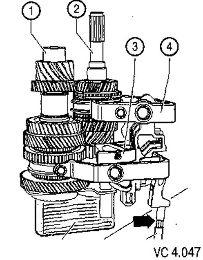
3. Install the reverse gear engagement fork (3).


4. Install the components into the gearbox. Before installing the bracket, ensure that the shift forks are properly seated in the gearbox housing.

5. Install the bracket together with the primary and secondary shafts by pressing it until it clicks into place.

6. Tighten the screw (A) securing the reverse gear shaft (see figure VC 4.046).

7. Remove the pivot pins (B) located on the top side of the gearbox.

8. Install the reversing light switch (C) (see figure VC 4.045).

9. Install the rotation axes (B) located on top of the gearbox housing.

10. To install the gear selection and engagement mechanism (A), set it to the neutral position and tighten the screws (arrows).

11. Using new screws (A), secure the input and output shaft bracket.

12. Tighten the hex nut (B) securing the gear shift mechanism.
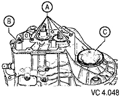
12. Tighten the hex nut (B) securing the gear shift mechanism.


13; Install the oil catch can (A) into the cutout (1) and hole (2) of the gearbox housing.
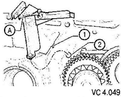


13; Install the oil catch can (A) into the cutout (1) and hole (2) of the gearbox housing.


14. Install the oil guide deflector (B) with the magnet installed in it into the gearbox housing.
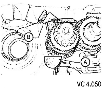
14. Install the oil guide deflector (B) with the magnet installed in it into the gearbox housing.


15. Install the differential (A) (see figure VC 4.043).

16. Secure the clutch housing to the gearbox housing.

17. Install the 5th gear pinion (1) with the protrusion towards the surface of the gearbox housing (arrow).

18. Install the 5th gear synchronizer sleeve with needle bearing.

19. Install the 5th gear synchronizer locking ring.

20. Install the hub with the 5th gear synchronizer sliding sleeve with the thrust washer.
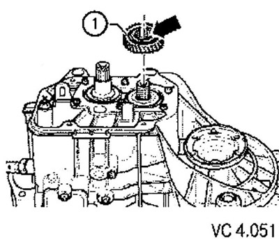
20. Install the hub with the 5th gear synchronizer sliding sleeve with the thrust washer.


21. Install the 5th gear shift fork (2) and the rotation axis (1) by pressing until it clicks into place in the direction of the arrow.


22. Determine the thickest thrust washers that will fit the primary (3) and secondary (4) shafts. Install new thrust washers (arrow).
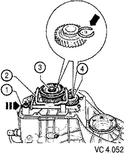
22. Determine the thickest thrust washers that will fit the primary (3) and secondary (4) shafts.…


23. Secure the gearbox housing cover.

24. Install both flanged shafts together with thrust washers, springs and tapered rings

25. Install the clutch release lever together with the release bearing and guide sleeve.

This article is available at russian, bulgarian, belarusian, ukrainian, serbian, croatian, romanian, polish, slovak, hungarian
The text has been checked: Kolesnikov Artem

Share information:

Previous articles
Disassembling the gearbox
Removal and installation of the primary shaft, secondary shaft, differential
Removal and installation the manual transmission housing
Removal and installation the gearbox housing cover and 5th gear wheels
Parts and components of the manual transmission type 0AH
Checking the oil level in the manual transmission
Next articles
Internal gear shift mechanism of a manual transmission
Disassembly and assembly of the internal gear shift mechanism
Dismantling and assembly of the primary shaft
Disassembly and assembly of the hub with a sliding sleeve of the synchronizer of 3rd and 4th gears
Checking the synchronizer locking ring for wear
Determining the thickness of the thrust ring


Similar articles from other manuals for VW cars:
Removal and installation the gearbox Passat B3 (1988-1993)
Gearbox 084 — engines 1.1 /1.3 l Golf 1 (1974-1984, petrol)
Disassembly and assembly of the gearbox Polo 3 (1995-2003)
Removal and installation of gearbox, cars with diesel engine R5 Touareg 1 (2002-2006)
Cylinder block from the gearbox side Tiguan 1 (2007-2015)
Removal and installation the gearbox from the engine Sharan 1 (1995-2000)
Gearbox and wheel drive Transporter T4 (1990-2003)
Link to this page in different formats


Visitor comments


No comments yet


How much will 36 + 45 =


Caddy 3 
  • General information
  • User manual
  • Daily care
  • Maintenance
  • Petrol engines 1.4 l
  • Engine repair
  • Cooling and lubrication system
  • Power and exhaust system
  • Petrol engines 1.6 l
  • Engine repair
  • Cooling and lubrication system
  • Power and exhaust system
  • Diesel engines
  • Engine repair
  • Cooling and lubrication system
  • Power and exhaust system
  • Transmission
  • Mechanical gearbox 0AH
  • Mechanical gearbox 0A4
  • Drive shafts
  • Chassis
  • Car suspension
  • Steering
  • Brake system
  • Body and wiring diagrams
  • Interior and exterior
  • Electrical circuits
Beetle 
  • General information
  • Maintenance
  • Power unit
  • Engine repair
  • Cooling and lubrication system
  • Supply system
  • Exhaust system
  • Transmission
  • Clutch
  • Car gearbox
  • Chassis
  • Front suspension
  • Rear suspension
  • Steering
  • Brake system
  • Wheels and tires
  • Body
  • Exterior
  • Electrical equipment
  • Equipment and devices
  • Power devices
  • Electrical circuits
LT 2D 
  • General information
  • User manual
  • Maintenance
  • Power unit
  • Petrol engines 2.3 l
  • Diesel engines 2.5 l
  • Diesel engines 2.8 l
  • Injection system (diesel 2.8 l)
  • Transmission
  • Clutch
  • Manual gearbox
  • Differential
  • Chassis
  • Car suspension
  • Steering system
  • Brake system
  • Body
  • Body elements
  • Heating system
  • Electrical equipment
  • Equipment and devices
  • Electrical circuits
LT 28 
  • General information
  • Maintenance
  • Power unit
  • Petrol engines 2.0L
  • Petrol engines 2.4L
  • Diesel engines
  • Cooling and heating
  • Fuel and exhaust system
  • Ignition system
  • Transmission
  • Clutch
  • Car gearbox
  • Cardan shaft
  • Rear axle
  • Chassis
  • Brake system
  • Car suspension
  • Steering system
  • Body
  • Body elements
  • Doors, locks and windows
  • Electrical equipment
  • Power devices
  • Equipment and devices
  • Electrical circuits
VWmanual.ru © 2016-2026 | Mobile version | News and articles | Sitemap: EN BG BY UA RS HR RO PL SK HU | Write message | Site search
Passat B2 • Passat B3 • Passat B4 • Passat B5 • Passat B6 • Golf 1, diesel • Golf 1, petrol • Golf 2, petrol • Golf 2 • Golf 3 • Golf 4 • Golf 5 • Polo 3 • Polo 4 • Touareg 1 • Tiguan 1 • Sharan 1 • Transporter T3 • Transporter T4 • LT 28 • LT 2D • Beetle • Caddy 3 •
Our website uses cookies to ensure functionality and convenience.