



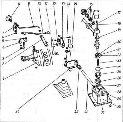
Figure 6.23. External gear selection mechanism
1 - bracket fixed to the gearbox; 2 longitudinal lever, 3-7 - elements of the switching unit; 8 - selector roller; 9 and 10 - transverse levers; 11 - ball joint; 12-15 - ball socket; 16 - bearing of the sliding lever; 17 - gear selection lever; 19 - plastic ring; 20, 21 and 22 - elements of the ball joint retaining cap; 23 - spring; 24 - ball; 25 - lower hinge plate; 23 plate; 27 - reflector; 28 - rivet; 29 - gasket; 30 - gear selector lever housing; 31 guide plates; 32 - longitudinal thrust; 33 - bushing; 34 - shift bracket.
2. During normal operation, all inserted bushings are subject to the greatest wear. If difficulties arise when shifting gears, then it is necessary to check the bushings of the connectors and cross rods, as well as the ball joints of the lever. Gaps in the connectors cause inaccurate installation of the selector shaft in the gearbox and difficulties in engaging gears.
Before removing the connector or lever, it is necessary to remember their position. Before removing the ball joint, it is necessary to first unfasten the latches.
3. To remove the longitudinal lever from the gear selector lever housing, it is necessary to disassemble the exhaust system.
4. Remove the longitudinal lever with the housing and gear selection lever downwards.
(The original information is posted on the resource VWmanual.ru)
Visitor comments