



Contents: Disassembly ↓ Assembly ↓
Disassembly
1. Secure the gearbox to the stand (figure 5.26a,b).
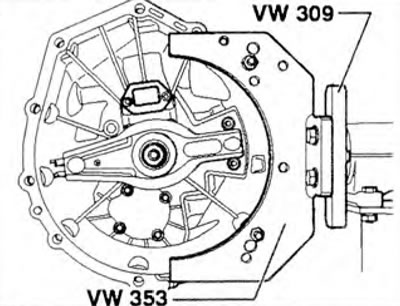
Figure 5.26a. Securing gearbox 000.1 on the stand.
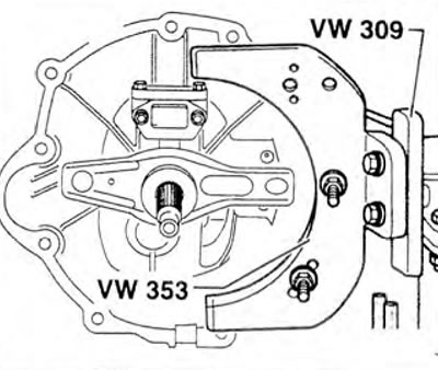
Figure 5.26b. Securing gearbox 000.2 on the stand.
2. Remove the clutch release lever together with the bearing.
3. Drain the oil from the gearbox.
4. Unscrew the guide bushing mounting bolts 1 and remove it (figure 5.27).
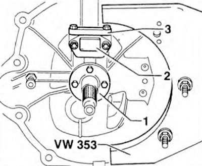
Figure 5.27. Unscrew the guide bushing mounting bolts 1 and remove it.
5. Remove the oil seal using a screwdriver (figure 5.28).
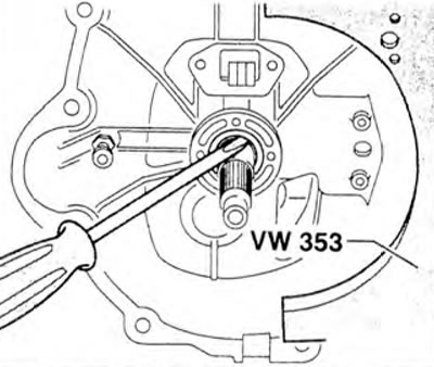
Figure 5.28. Remove the oil seal using a screwdriver.
6. Remove the retaining ring from the input shaft (figure 5.29).
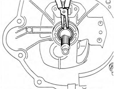
Figure 5.29. Remove the retaining ring from the input shaft.
7. Unscrew the flange mounting bolt A (figure 5.30).
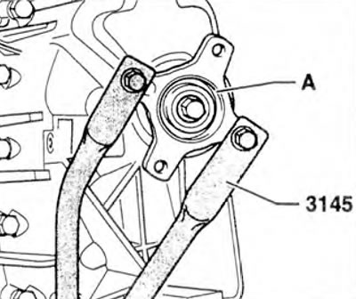
Figure 5.30. Loosen the flange A mounting bolt.
8. Remove the flange from the secondary shaft (figure 5.31).
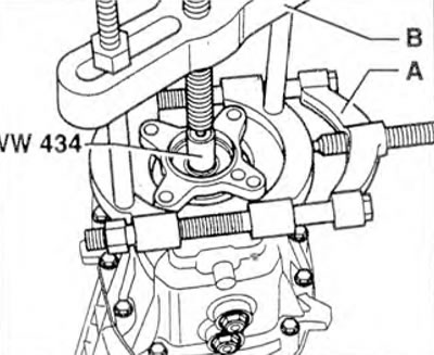
Figure 5.31. Remove the flange from the secondary shaft: A. Kukko puller (22-115 mm), B. Kukko bracket.
9. Using a screwdriver, carefully remove the oil seal from the gearbox housing.
10. Remove the speed sensor rotor and, if necessary, the sleeve from the secondary shaft.
11. Unscrew the bolts 1 securing the gear shift forks (figure 5.32). Remove the 2 reverse light switch. Then remove the bushing, remove the pin with the spring and the ball bushing from the hole. Unscrew plug 3 and remove the spring with the ball bushing from the hole.
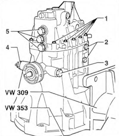
Figure 5.32. Unscrew bolts 1 securing the gear shift forks. Remove switch 2 of the reversing lights and unscrew plug 3.
12. Using a punch, remove pin 1 of the gear shift lever and remove lever 2 (figure 5.33).
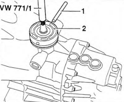
Figure 5.33. Using a punch, remove pin 1 of the gear shift lever and remove lever 2.
13. Unscrew both bolts 1 securing the reverse gear shaft (figure 5.34). Unscrew the 2 bolts securing the gearbox housing to the clutch housing. Using a plastic hammer, carefully pry the gearbox housing away from the housing. Remove the reverse gear shaft.
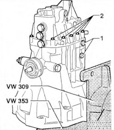
Figure 5.34. Unscrew both bolts 1 securing the reverse gear shaft and bolts 2 securing the gearbox housing to the clutch housing.
14. Unscrew the mounting bolts (arrows) of the guide sleeve (figure 5.35).
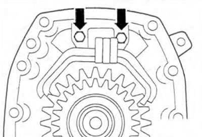
Figure 5.35. Unscrew the mounting bolts (arrows) of the guide sleeve.
15. Using the VW421 tubular puller, press out the intermediate and secondary shafts together with the gear shift forks from the gearbox housing (figure 5.36).
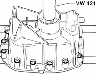
Figure 5.36. Using the VW421 tubular puller, press out the intermediate and secondary shafts together with the gear shift forks from the gearbox housing.
The text is copied from this portal: VWMANUAL
16. Using pullers VW407 and VW421, press the input shaft out of the clutch housing (figure 5.37).
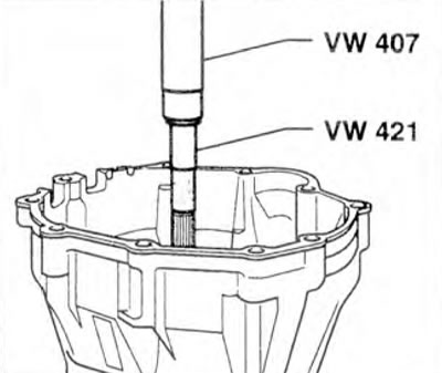
Figure 5.37. Using pullers VW407 and VW421, press the input shaft out of the clutch housing.
Assembly
17. Lubricate the sealing surfaces of the clutch housing and gearbox.
18. Install the intermediate shaft, secondary shaft and forks 1 together with the guide sleeve into the gearbox housing and press in using the VW 407 puller (figure 5.38).
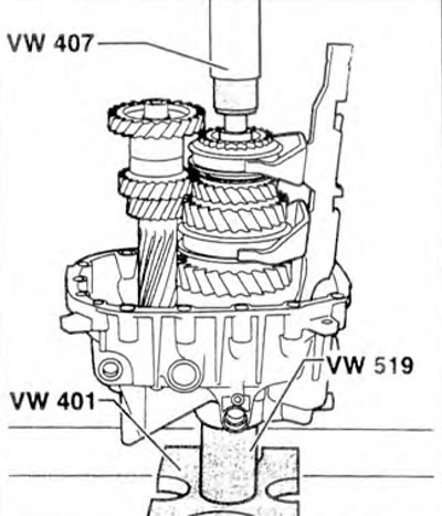
Figure 5.38. Install the intermediate shaft, secondary shaft and forks 1 together with the guide sleeve into the gearbox housing and press in using the VW 407 puller.
19. If necessary, move forks 1 and sliding bushings so that grooves 2 of all three forks are aligned in the neutral gear position.
20. Installation position of the rear shift forks: The hole (arrow) for the shift forks must always be on the right (or on the left in the direction of travel) (figure 5.39). Different versions of the guide bushing are shown in the figure 5.40 Version C can be used on all gearboxes.
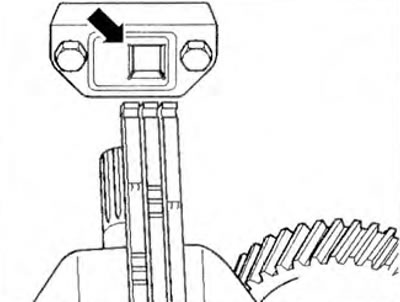
Figure 5.39. Installation position of the rear shift forks: the hole (arrow) for the shift forks must always be on the right (or on the left in the direction of travel).
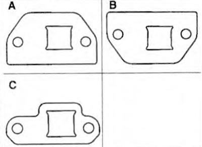
Figure 5.40. Different versions of the guide bushing: A - Guide sleeve manual transmission 000.1; B - Guide sleeve manual transmission 000.2; C - Guide bushing with new outer contour.
21. Screw in both bolts (arrows) securing the guide bushing (figure 5.35).
22. Adjust the protrusion "a" of the reverse gear shaft pin to a distance of 46.5-47.0 mm (figure 5.41).
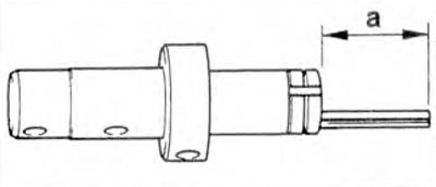
Figure 5.41. Adjust the protrusion "a" of the reverse gear shaft pin.
23. Install the reverse gear shaft together with the gear into the gearbox housing.
24. Insert pin 1 into the hole (arrow) in the gearbox housing (figure 5.42). Rotate the reverse gear shaft so that the gear is positioned in the teeth of the gears on the intermediate and primary shafts, and the holes 2 are positioned outward towards the housing. Using pullers VW 407 and VW 421, press the input shaft into the roller bearing in the clutch housing.
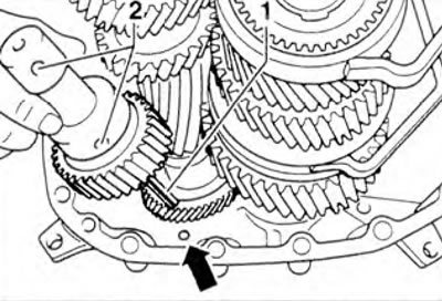
Figure 5.42. Insert pin 1 into the hole (arrow) in the gearbox housing.
25. Lubricate the clean sealing surfaces of the gearbox housing with AMV 188 200 03 sealant.
26. Install bearing 1 of the primary shaft onto secondary shaft 2 (figure 5.43).
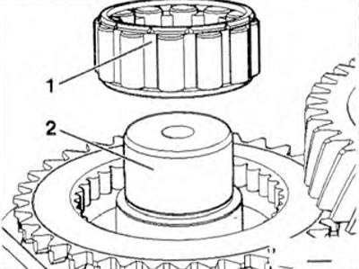
Figure 5.43. Install bearing 1 of the primary shaft onto secondary shaft 2.
27. Install the clutch housing onto the gearbox housing.
28. Install and tighten the reverse gear shaft mounting bolts A (arrows) (figure 5.44).
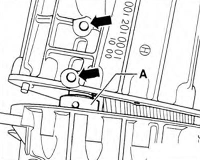
Figure 5.44. Install and tighten the reverse gear shaft mounting bolts A (arrows).
29. Secure the gearbox housing and clutch housing with new bolts.
Tightening torque: 20 Nm.
30. Install the gear shift lever assembly.
31. Install the retaining ring on the input shaft (figure 5.29).
32. Install the new oil seal until it stops and make sure that it does not rotate (figure 5.45).
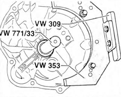
Figure 5.45. Install the new oil seal until it stops and make sure that it does not rotate.
33. Install the sealing ring and three locking pins into the shift fork guide bushing with the flattened side facing into the shift forks (figure 5.27). Install two balls, lubricated with viscose grease, into plate 3 and secure the plate to the guide sleeve. Tighten the mounting bolts by hand. Secure the guide sleeve with cover 2 in accordance with the marks made during removal. Tighten plate mounting bolts 3 to 20 Nm. Install guide sleeve 1 and tighten it. Lubricate the clutch release bearing, bearing guide sleeve and input shaft splines with G 000 100 grease. Install the clutch release lever with bearing onto the guide sleeve and ball head.
Attention! Depending on the type of gearbox, the front guide bushing can be installed with the plate 3 surface facing up or down (figure 5.27).
34. On manual transmission 000.1: install the speedometer sensor rotor 1 and, if necessary, the sleeve 2 (figure 5.46). On manual transmission 000.2; install the speedometer sensor rotor 7 and, if necessary, the sleeve 8. Using the installation sleeve 4-20, install the new oil seal 3 into the gearbox housing, making sure that the oil seal does not rotate. Install flange 4 on the secondary shaft and tighten bolt 6 with washer 5.
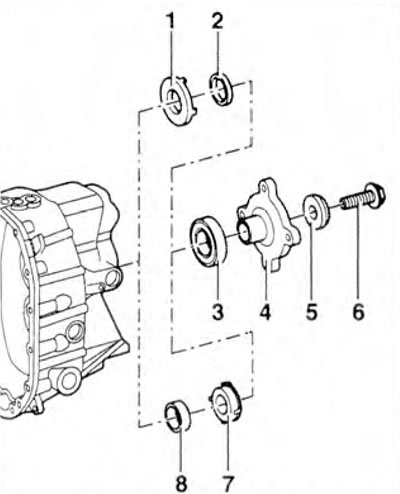
Figure 5.46. On manual transmission 000.1: install speedometer sensor rotor 1 and, if necessary, sleeve 2. On manual transmission 000.2: install speedometer sensor rotor 7 and, if necessary, sleeve 8. Using installation sleeve 4-20, install new oil seal 3 into the gearbox housing, making sure that the oil seal does not turn. Install flange 4 on the secondary shaft and tighten bolt 6 with washer 5.
Attention! Sleeve 2 is not installed on all gearboxes.
35. Install bracket 3145 on the flange and tighten flange mounting bolt A (figure 5.30).
Visitor comments