



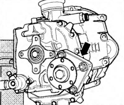
Figure 5.74. The PTO is installed in the rear part of the 000.1 gearbox (arrow) as additional equipment.
Operating principle
The PTO is driven from the intermediate shaft 1 of the manual transmission through the drive part 2 with gear 3 (figure 5.75). This gear drives shaft 4 with flange 5 or the gear of an additional unit directly (not shown).
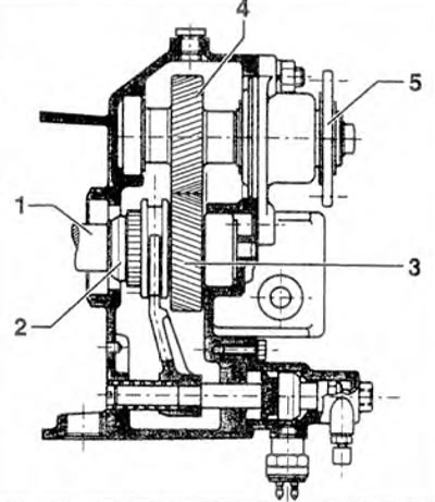
Figure 5.75. Operating principle of the PTO.
The original can be viewed on the portal www.vwmanual.ru
Switching mechanism (shutdown) COM
Switching mechanism (shutdown) KOM - electropneumatic (figure 5.76a). When the PTO is turned on, a signal light on the panel lights up and remains on as long as the PTO is turned on. The general appearance of the PTO is shown in the figure 576b.
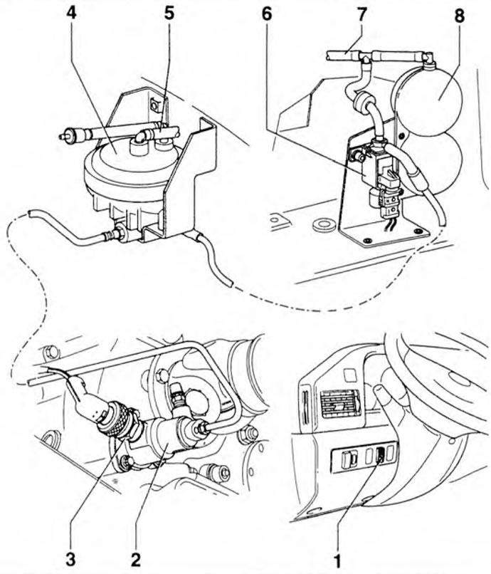
Figure 5.76a. Switching mechanism (shutdown) COM: 1 - PTO switch; 2 - PTO engagement cylinder; 3 - PTO indicator light switch; 4 - Converter; 5 - Tube to the brake fluid reservoir; 6 - PTO valve; 7 - Tube to the brake booster; 8 - Vacuum tank.
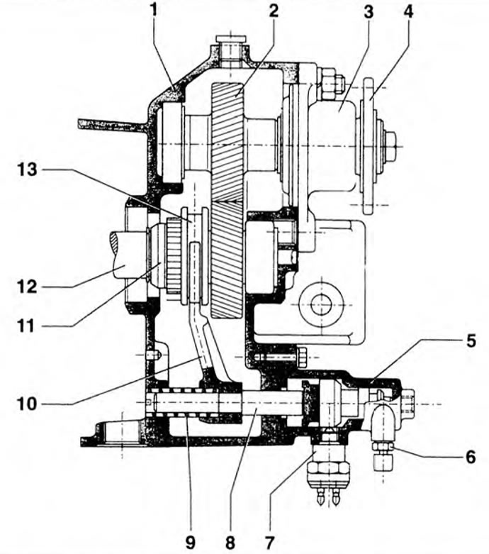
Figure 5.76b. General view of the KOM: 1 - Gearbox housing; 2 - PTO shaft, 3 - Housing cover; 4 - Flange; 5 - On/off cylinder; 6 - Air bleed valve; 7 - PTO switch; 8 - Power lever; 9 - Spring; 10 - Power fork; 11 - Drive shaft; 12 - Intermediate shaft; 13 - Engagement clutch.
Visitor comments