



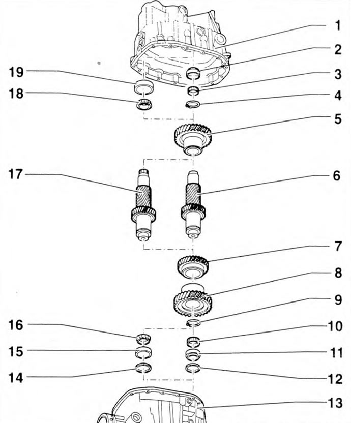
Figure 5.57. Intermediate shaft: 1 - Gearbox housing; 2, 11 - Outer rings of roller bearings (Manual transmission 000.2); 3 - Roller bearing (Manual transmission 000.2); 4 - 5th gear retaining ring; 5 - 5th gear pinion; 6 - Intermediate shaft (Manual transmission 000.2); 7 - 3rd gear pinion; 8 - 4th gear pinion; 10 - 4th gear retaining ring; 12 - Adjusting washer (Manual transmission 000.2); 13 - Clutch housing; 14 - Adjusting washer (Manual transmission 000.1); 15, 19 - Outer rings of tapered roller bearings (Manual transmission 000.1); 16, 18 - Inner rings of tapered roller bearings (Manual transmission 000.1); 17 - Intermediate shaft (Manual transmission 000.1).
Removing the outer ring of the roller bearing from the gearbox housing is shown in the figure 5.58a, installation - in figure 5.58b. Removal is carried out using the VW 771/37 and WV 771 keys, installation - using the VW 510 thrust part and the VW295 punch.

Figure 5.58a. Removing the outer ring of the roller bearing from the gearbox housing.
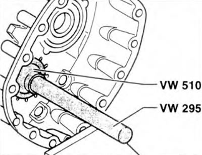
Figure 5.58b. Installing the outer ring of the roller bearing into the gearbox housing.
Removing the 5th gear is shown in the figure 5.59a, installation - in figure 5.59b.
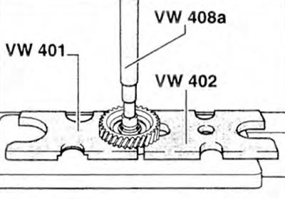
Figure 5.59a. Removing the 5th gear.
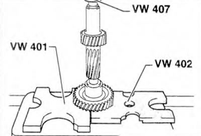
Figure 5.59b. Installing the 5th gear.
Removing the 3rd gear is shown in the figure 5.60a, installation - in figure 5.60b.
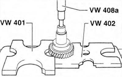
Figure 5.60a. Removing the 3rd gear.
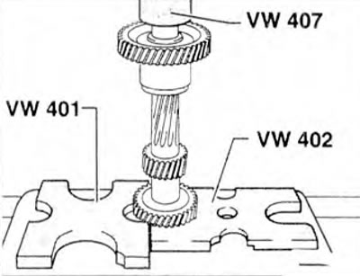
Figure 5.60b. Installing the 3rd gear.
Removing the 4th gear is shown in the figure 5.61a, installation - in figure 5.61b.
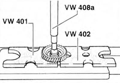
Figure 5.61a. Removing the 4th gear.
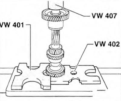
Figure 5.61b. Installing the 4th gear.
Removing the inner race of the tapered roller bearing from the gearbox housing is shown in the figure 5.62a, installation - in figure 5.62b.
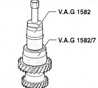
Figure 5.62a. Removing the inner race of the tapered roller bearing from the gearbox housing.
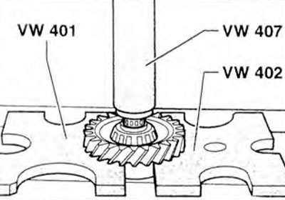
Figure 5.62b. Installing the inner ring of a tapered roller bearing into the gearbox housing.
Removing the outer race of the tapered roller bearing from the gearbox housing is shown in the figure 5.63a, installation - in figure 5.63b.
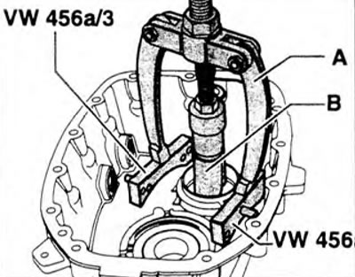
Figure 5.63a. Removing the outer race of the tapered roller bearing from the gearbox housing: A. Kukko puller (46-58 mm), c. Kukko bracket.
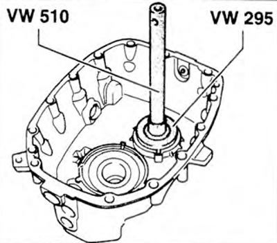
Figure 5.63b. Installing the outer ring of a tapered roller bearing into the gearbox housing.
Adjusting the intermediate shaft bearing (Manual transmission 000.1)
1. Remove cover 1 and the adjusting gasket located underneath it (figure 5.64).
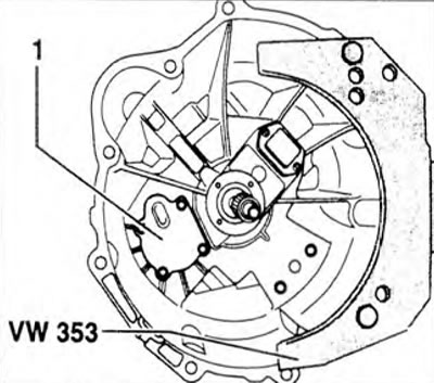
Figure 5.64. Remove cover 1 and the adjusting gasket located underneath it.
2. Remove any remaining gasket from the sealing surface of the cover.
3. Install the four supports (arrows) of clamp 3117 on the outer ring of the tapered roller bearing (figure 5.65). Remove the hinges and spindle of puller 3032. Carefully secure the tool with two bolts 1.
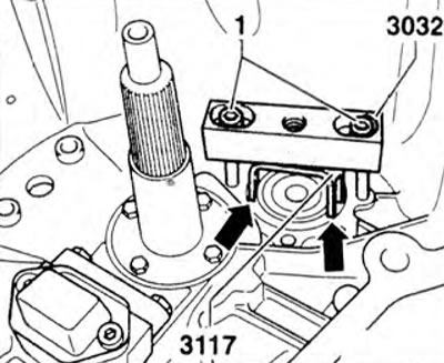
Figure 5.65. Install the four supports (arrows) of clamp 3117 on the outer ring of the tapered roller bearing. Remove the hinges and spindle of puller 3032. Carefully secure the tool with two bolts 1.
4. Remove the clutch release lever together with the bearing.
5. Install the guide pin (arrow) on the outer ring and set the indicator to "0" with a preload of 2 mm (figure 5.66).
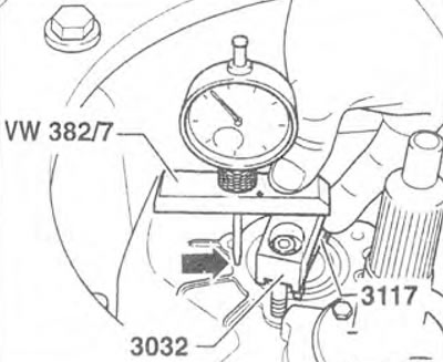
Figure 5.66. Install the guide pin (arrow) on the outer ring of the tapered roller bearing and set the indicator to "0" with a preload of 2 mm.
6. Place the guide pin (arrow) on the sealing surface and measure the distance. Repeat the measurement on the other side of tool 3032 and determine the distance to the opposite side of the tapered roller bearing outer ring in relation to the sealing surface (figure 5.67).
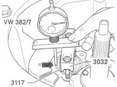
Figure 5.67. Place the template finger (arrow) on the sealing surface and measure the distance. Repeat the measurement on the other side of Tool 3032 and determine the distance to the opposite side of the tapered roller bearing outer ring in relation to the sealing surface.
7. Using the values obtained from both measurements, determine the thickness of the adjusting shim. For example, the first measurement is 2.62 mm, the second measurement is +2.68 mm. The resulting value is 5.30 mm / 2 = 2.65 mm. The thickness of the adjusting shim is 2.65 mm.
8. Remove the measuring devices and install an adjusting shim of the required thickness.
9. Install cover 1 (figure 5.64).
Adjusting the intermediate shaft bearing (Manual transmission 000.2)
10. Install a variable thickness shim in place of the adjusting shim under the outer race of the roller bearing in the gearbox housing or clutch housing.
Please note: The thickness of the adjusting shims varies from 1.50 to 4.40 mm.
11. Install intermediate shaft 1 with roller bearing (figure 5.68). Tighten the four transmission housing to clutch housing bolts.
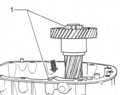
Figure 5.68. Install intermediate shaft 1 with roller bearing.
12. Install the gearbox vertically with the gearbox housing facing up. Unscrew the filler plug.
13. Attach the indicator to the gearbox housing so that the alignment pin can be directed into the secondary shaft hole (figure 5.69).
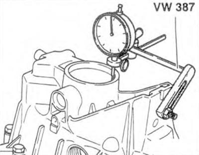
Figure 5.69. Attach the indicator to the gearbox housing so that the alignment pin can be directed into the secondary shaft hole.
14. Place the indicator pin (arrow) on the 5th gear and set the indicator arrow to "0" (figure 5.70).

Figure 5.70. Place the indicator pin (arrow) on the 5th gear and set the indicator arrow to "0".
15. Pass the lever through the filler hole and install it under the 5th gear (arrow) (figure 5.71).
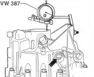
Figure 5.71. Pass the lever through the filler hole and install it under the 5th gear (arrow).
16. Carefully lift the lever up (arrow) and measure the gap on the indicator (figure 5.72). Set the gap to 0 mm by selecting an adjusting shim of the required thickness.
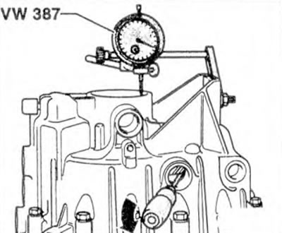
Figure 5.72. Carefully lift the lever up (arrow) and measure the gap on the indicator.
Visitor comments