



Contents: Checking the installation of the…↓ Adjusting the primary shaft ↓ Secondary shaft adjustment (Manual…↓
The gearbox shafts are shown in the figure 5.48.
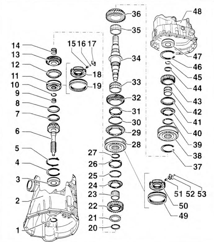
Figure 5.48. Gearbox shafts: 1, 4, 5, 10, 20, 27, 37, 39, 45, 46 - Retaining rings; 2 - Clutch housing; 3, 47 - Ball bearings; 6 - Primary shaft; 7 - 4th gear synchronizer ring; 8 - 4th gear cone ring; 9 - Secondary shaft needle bearing; 11 - Clutch with synchronizer hub for 3rd and 4th gears; 12 - 2nd gear synchronizer ring; 13 - 3rd gear pinion; 14 - 3rd gear needle bearing; 15, 51 - Springs; 16, 53 - Balls; 17, 52 - Blocking plates; 18 - 3rd and 4th gear synchronizer hub; 19 - 3rd and 4th gear synchronizer clutch; 21, 44 - Thrust washers; 22 - 2nd gear pinion; 23 - 2nd gear needle bearing; 24 - 2nd gear synchronizer ring; 25 - 2nd gear cone ring; 26 - 2nd gear synchronizer inner ring; 28 - Clutch with synchronizer hub for 1st and 2nd gears; 29 - 1st gear synchronizer ring; 30 - 1st gear cone ring; 31 - Inner ring of 1st gear synchronizer; 32 - 1st gear pinion; 33 - 1st gear needle bearing; 34 - Secondary shaft; 35 - Reverse gear needle bearing; 36 - Reverse gear; 38 - Clutch with hub of synchronizer of 5th gear and reverse gear; 40 - 5th gear synchronizer ring; 41 - 5th gear cone ring; 42 - 5th gear needle bearing; 43 - 5th gear pinion; 48 - Gearbox housing; 49 - 1st and 2nd gear synchronizer clutch; 50 - 1st and 2nd gear synchronizer hub.
Removing the ball bearing is shown in the figure 5.49a, installation - in figure 5.49b.
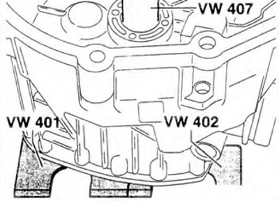
Figure 5.49a. Removing the ball bearing using the VW 407 puller.
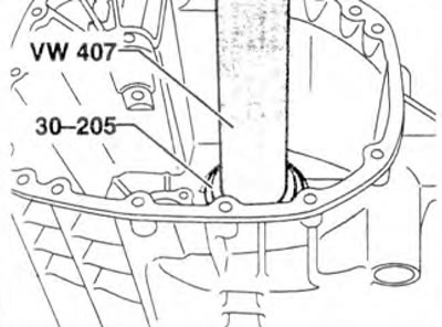
Figure 5.49b. Installing a ball bearing using a VW 407 puller and a 30-205 plate.
The installation of the retaining ring is shown in the figure 5.50. After installation it should not cover the oil hole (arrow).
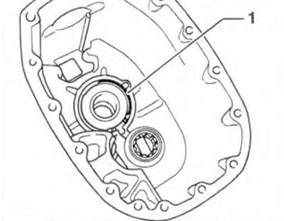
Figure 5.50. Installing retaining ring 1.
Removing the ball bearing is shown in the figure 5.51a, installation - in figure 5.51b.
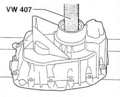
Figure 5.51a. Removing a ball bearing using the WV 407 puller.
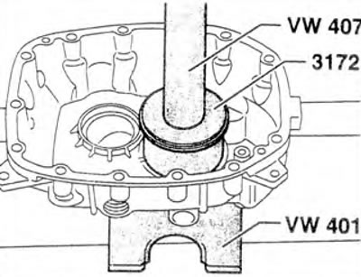
Figure 5.51b. Installing a ball bearing using a VW 407 puller and a 3172 plate.
Removing the 2nd gear is shown in the figure 5.52.
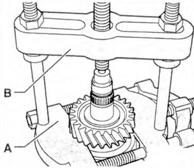
Figure 5.52. Removing the 2nd gear: A. Kukko puller (22-115 mm), B. Kukko bracket.
Checking the 1st and 2nd gear synchronizer ring is shown in the figure 5.53a. Install the synchronizer ring, outer and inner rings on the cone ring of the gear and measure the gap "a" using a feeler gauge. Installation distance: 1.00-1.50 mm. Permissible wear: 0.5 mm.
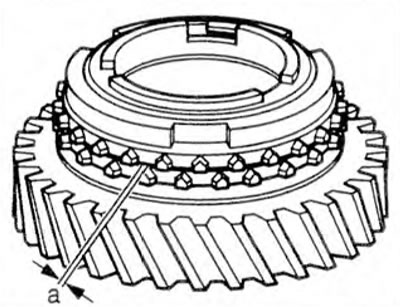
Figure 5.53a. Checking the 1st and 2nd gear synchronizer ring.
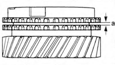
Figure 5.53b. Checking the synchronizer ring of 3rd/4th gear and 5th gear/reverse gear.
Checking the installation of the primary shaft
1. Set clutches 1 to neutral position. Install three forks with rods on couplings 1. Grooves 2 on the rods must be located on the same line (figure 5.54).
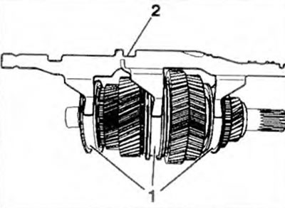
Figure 5.54. Set couplings 1 to neutral position. Install three forks with rods on couplings 1. Grooves 2 on the rods must be located on the same line.
Adjusting the primary shaft
2. Using a feeler gauge, measure the clearance between the ball bearing and the retaining ring at three points (figure 5.55). Determine the thickness of the retaining ring and install a new one.
For example, a 2.70 mm thick retaining ring is installed.
- 1st measurement - 0.15 mm;
- 2nd dimension - + 0.12 mm;
- 3rd dimension - + 0.13 mm.
The total value is 0.40 mm / 3 = 0.13 mm. Replace the retaining ring with a new one with a thickness of 2.78 mm (taking into account the residual runout of at least 0.30 mm).
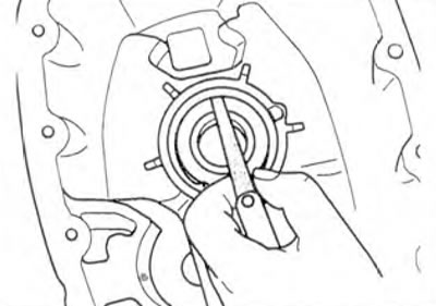
Figure 5.55. Adjusting the primary shaft.
Secondary shaft adjustment (Manual transmission 000.1)
3. Using a feeler gauge, measure the clearance between the ball bearing and the retaining ring at three points (figure 5.56). Determine the thickness of the retaining ring and install a new one.
For example, a 2.70 mm thick retaining ring is installed.
For example, a 2.70 mm thick retaining ring is installed.
- 1st measurement - 0.15 mm;
- 2nd dimension - + 0.12 mm;
- 3rd dimension - + 0.13 mm.
The total value is 0.40 mm/3 = 0.13 mm. Replace the retaining ring with a new one with a thickness of 2.78 mm (taking into account the residual runout of at least 0.30 mm).
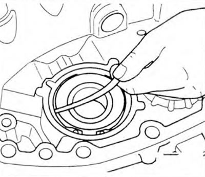
Figure 5.56. Adjusting the secondary shaft.
Visitor comments