



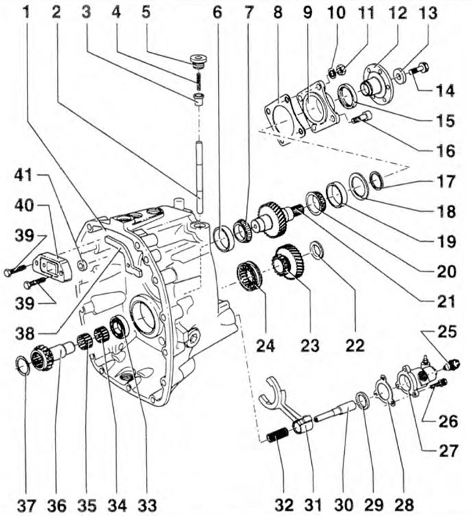
Figure 5.81. Flange, shaft, drive gear and PTO engagement mechanism: 1 - Gearbox housing; 2 - Control rod; 3 - Stop; 4 - Spring; 5 - Cork; 6, 19 - Outer rings of tapered roller bearings; 7, 20 - Inner rings of tapered roller bearings; 8, 28, 37 - Gaskets; 9 - Lid; 10, 13 - Washers; 11 - Nut; 12 - Flange; 14, 16, 26, 39 - Bolts; 15 - Seal; 17, 29, 41 - Bushings; 18 - Gasket(s); 21 - PTO shaft; 22 - Thrust gasket; 23 - Gear; 24 Coupling; 25 Switch KOM; 27 Working cylinder; 31 Shift fork; 32 - Spring; 33 - Cylindrical roller bearing; 34, 35 - Needle bearings; 36 - Drive shaft; 38 - Locking pawl; 40 - Guide sleeve.
Adjusting the axial clearance of the drive shaft
1. Determine the distance "a" from the edge of the intermediate shaft 1 to the retaining ring 2 (figure 5.82).
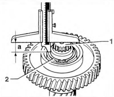
Figure 5.82. Determine the distance "a" from the edge of intermediate shaft 1 to retaining ring 2.
2. Determine the distance "b" from the edge of the intermediate shaft 1 to the outer ring 2 of the bearing (figure 5.83).
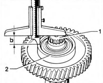
Figure 5.83. Determine the distance "b" from the edge of the intermediate shaft 1 to the outer ring 2 of the bearing.
3. Determine the distance "c" from the top edge to the bearing seat in the gearbox housing (figure 5.84).
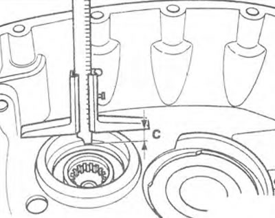
Figure 5.84. Determine the distance "c" from the top edge to the bearing seat in the gearbox housing.
4. Determine the distance "d" from the upper edge of the bearing hole to the drive shaft 1 in the gearbox housing (figure 5.85).
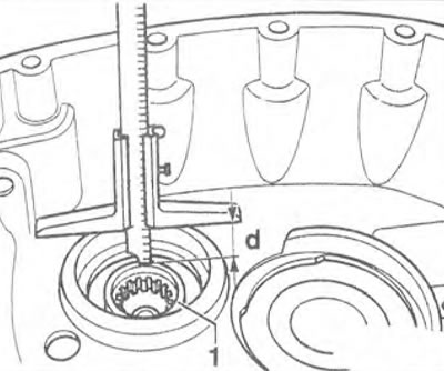
Figure 5.85. Determine the distance "b" from the upper edge of the bearing hole to the drive shaft 1 in the gearbox housing.
5. Determine the thickness of the adjusting shim(s) (figure 5.86).
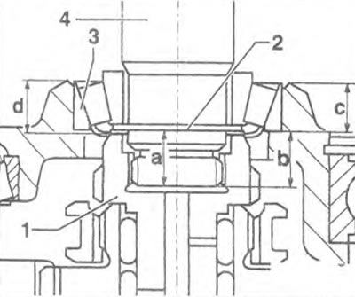
Figure 5.86. Determine the thickness of the adjusting shim(s).
- Distance "b" 16.4 mm - Distance "a" 16.3 mm = Distance "e" 0.1 mm.
- Distance "d" 15.0 mm - Distance "c" 14.4 mm = Distance "c" 0.6 mm.
- Distance "e" 0.1 mm + Distance "f" 0.6 mm = Resulting axial clearance 0.7 mm.
- Permissible axial clearance 0.1-0.2 mm.
- Resulting axial clearance 0.7 mm - Allowable axial clearance 0.1 mm = Thickness of adjusting shim 0.6 mm.
Attention! The thickness of the adjusting shim is 0.2 and 0.3 mm.
6. Install adjusting shim(s) 1 onto intermediate shaft 2 (figure 5.87).
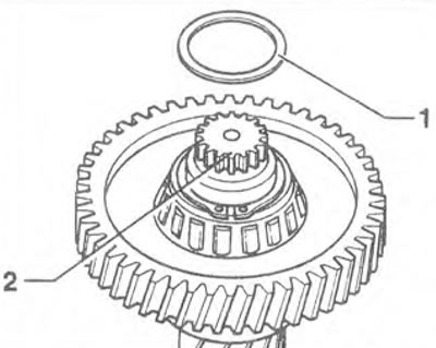
Figure 5.87. Install adjusting shim(s) 1 on intermediate shaft 2.
Adjusting the PTO shaft
7. Install shaft 1 with outer ring 2 of the bearing into the gearbox housing (figure 5.88). Set the shaft to the middle position and secure it with 30-211 A strips and nuts on the housing.
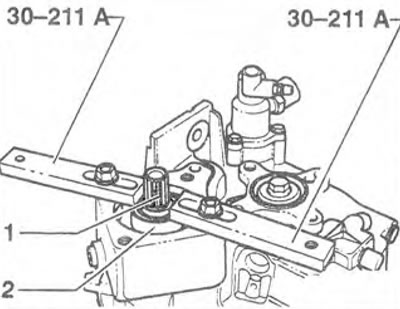
Figure 5.88. Install shaft 1 with outer ring 2 of the bearing into the gearbox housing. Set the shaft to the middle position and secure it with 30-211 A strips and nuts on the housing
8. Measure the distance "a" between the outer ring 1 of the bearing and the sealing surface of the housing at two opposite points (figure 5.89). For example, 1st dimension 3.5 mm + 2nd dimension = total 7.1 mm. Distance "a" = 7.1 mm / 2 = 3.55 mm.
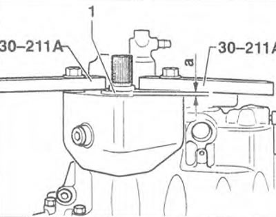
Figure 5.89. Measure the distance "a" between the outer ring 1 of the bearing and the sealing surface of the housing at two opposite points.
9. Disconnect the strips and remove the outer ring 1 of the bearing.
10. Install a new gasket 1 on the housing cover 2 and determine the distance "b" of the parallel support to the contact surface of the outer ring of the bearing in the cover (figure 5.90).
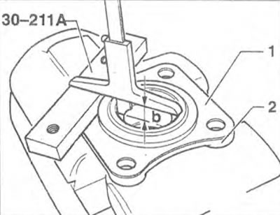
Figure 5.90. Install new gasket 1 on cover 2 of the housing and determine the distance "b" of the parallel support to the contact surface of the outer ring of the bearing in the cover
11. Determine the axial clearance of the PTO shaft (figure 5.91). Distance "b" 19.5 mm - Distance "a" 15.1 mm = Distance "c" 4.4 mm. Distance "c" 4.40 mm - Distance "a" 3.55 mm = axial clearance of the PTO shaft 0.85 mm.
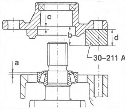
Figure 5.91. Determine the axial clearance of the PTO shaft.
Attention! Thickness of the adjusting shim: 0.10. 0.15. 0.30 and 0.50 mm.
12. Install the selected adjusting shim(s) 1 into the housing cover 2 (figure 5.92).
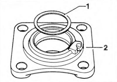
Figure 5.92. Install the selected adjusting shim(s) 1 into the housing cover 2.
13. Press the outer bearing ring into the housing cover (figure 5.93).
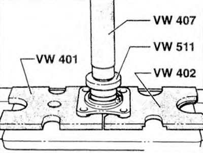
Figure 5.93. Press the outer bearing ring into the housing cover.
Visitor comments