
English Русский
Български
Беларускі
Український
Српски
Hrvatski
Română
Polski
Slovenský
Magyar
  |  Articles  |  Sitemap  |  Contacts  |    |
Car maintenance Ford Car maintenance Hyundai Car maintenance Chevrolet Car maintenance BMW Car maintenance Audi Car maintenance Opel Car maintenance AvtoVAZ
VWmanual.ru


Main   Passat   Golf   Polo   Touareg   Tiguan   Sharan   Transporter   Others  
Transporter T3 (1979-1992) Transporter T4 (1990-2003)

Disassembly and assembly of front drive axle shafts (VW Transporter T4)

  • Main
  • Transporter
  • Transporter T4
  • Chassis
  • Car suspension
  • Disassembly and assembly of front drive axle shafts
            0


Contents: Disassembly ↓ Assembly ↓

Disassembling the axle shaft
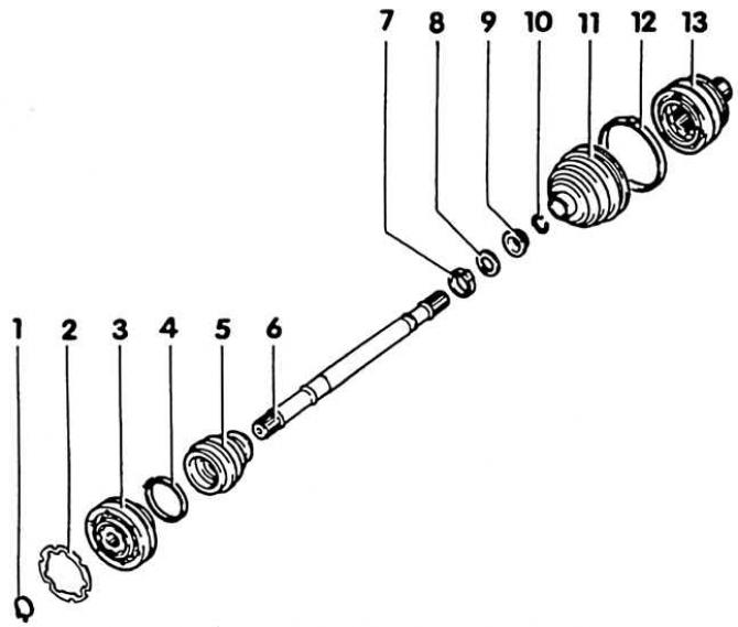


1. Safety washer; 2. Gasket; 3. Internal articulated synchronizer; 4. Clamp; 5. Protective cover of…

1. Safety washer; 2. Gasket; 3. Internal articulated synchronizer; 4. Clamp; 5. Protective cover of the articulated synchronizer. Check for abrasions and cuts!; 6. Half shaft 7. Clamp; 8. Disc spring; 9. Sliding ring; 10. Safety washer; 11. Protective cover of the outer articulated synchronizer; 12. Sleeve clamp; 13. External articulated synchronizer


Disassembly


1. Remove the axle shaft.

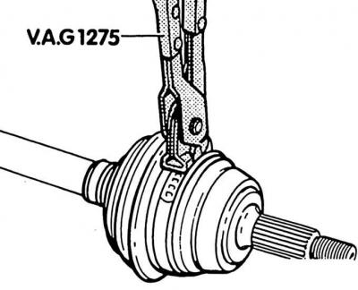
2. Cut the sleeve clamps on both sides of the hinge protective cover with pliers and remove. Move the cover back.
2. Cut the sleeve clamps on both sides of the hinge protective cover with pliers and remove. Move…


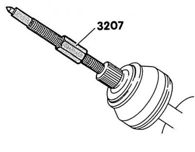
3. Press out the outer joint. To do this, install the axle shaft in a vice with protected jaws and clamp it. Turn the cover in the opposite direction. Screw in the KAG-3207 device with the M16 threaded part until the synchronizer joint is pressed out of the profile shaft.


4. Inner joint: squeeze and remove the retaining ring (1) with suitable round-nose pliers – see Fig. Disassembling the axle shaft.

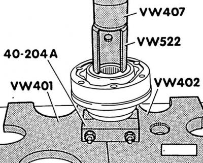
5. Press out the inner joint with a suitable press, while pushing against the ball hub.

The original can be viewed on the portal [VWmanual]

6. Inner joint: remove the gasket (2) – see Fig. Disassembling the axle shaft.

Assembly


1. Replace brittle or faulty axle shaft covers.

2. Place protective covers with sleeve clamps on the shaft.

3. Place the disc spring (8) and sliding ring (9) on the profile shaft. Install the disc spring correctly (see Fig. Disassembling the axle shaft). Large diameter disc spring (concave side) rests against the sliding ring.

4. Install a new safety washer into the shaft groove.

5. Lubricate the outer joint with 120 g of VWG-6.3 grease. Press about 80 g of grease through the inner splines of the ball hub into the outer joint. Apply about 40 g of grease to the inner side of the joint.

Attention! If only the hinge protective cover is to be replaced, add lubricant if necessary.


6. Using a plastic hammer, press the outer joint onto the shaft until it is secured by the safety washer.
6. Using a plastic hammer, press the outer joint onto the shaft until it is secured by the safety…


7. Place the protective cover on the joint and install the sleeve clamp on the larger diameter using suitable pliers.


Attention! Often when putting on the protective cover on the hinge body, it is pressed. As a result, a vacuum is formed above the cover, which during operation draws the grease inside. Therefore, after installation, using a screwdriver, from the side of the smaller diameter, it is necessary to slightly lift the cover and equalize the pressure.


8. Place the sleeve clamp on the smaller diameter.

9. Inner joint: Press 120 g of VWG-6.3 grease into each side of the joint. If only the joint boot is being replaced, add grease as needed.
9. Inner joint: Press 120 g of VWG-6.3 grease into each side of the joint. If only the joint boot…


10. Press the inner joint in with a suitable press until it stops.

11. Install a new safety washer into the shaft groove using round-nose pliers.

12. Inner hinge: secure the protective cover with a sleeve clamp and attach a new gasket to the hinge, after removing the protective chamfer from it.

13. Install the axle shaft.

This article is available at russian, bulgarian, belarusian, ukrainian, serbian, croatian, romanian, polish, slovak, hungarian
The text has been checked: Orlov Dmitry

Share information:

Previous articles
Removal and installation front drive axle shafts
Shock absorber — removal and installation
Upper steering knuckle support
General information about the front suspension
Front suspension — design description
Next articles
Rear suspension — design description
General information about the rear suspension
Removal and installation the rear shock absorber
Checking the rear shock absorber
Rear shock absorber coil spring


Similar articles from other manuals for VW cars:
Removal and installation front wheel drive shafts Passat B2 (1981-1988)
Front drive shafts Golf 3 (1991-1997)
Constant velocity joint axle shafts Polo 3 (1995-2003)
Checking the oil level in the main gear of the front axle Touareg 1 (2002-2006)
Removal and installation of rear axle ABS system components… Tiguan 1 (2007-2015)
Wheel Drive Shafts — Design Description Sharan 1 (1995-2000)
General description of drive shafts Caddy 3 (2003-2010)
Link to this page in different formats


Visitor comments


No comments yet


How much will 36 + 41 =


Transporter T4 
  • General information
  • User manual
  • Maintenance
  • Power unit
  • Engine repair
  • Ignition system
  • Lubrication system
  • Cooling system
  • Fuel system (petrol)
  • Fuel system (diesel)
  • Injection system (petrol)
  • Exhaust system
  • Transmission
  • Clutch
  • Car gearbox
  • Chassis
  • Car suspension
  • Steering
  • Brake system
  • Wheels and tires
  • Body
  • Exterior
  • Interior
  • Doors and windows
  • Heating system
  • Electrical equipment
  • Equipment and devices
  • Lighting and signaling
  • Power devices
  • Electrical circuits
Transporter T3 
  • General information
  • Maintenance
  • Petrol engines
  • Engine repair
  • Lubrication system
  • Cooling system
  • Power and exhaust system
  • Carburetor 34 PICT
  • Carburetors 2E3 and 2E4
  • Fuel injection system
  • Ignition system
  • Diesel engines
  • Engine repair
  • Lubrication system
  • Cooling system
  • Power and exhaust system
  • Transmission
  • Clutch
  • Car gearbox
  • Chassis
  • Front suspension
  • Rear suspension
  • Steering
  • Brake system
  • Body
  • Body and interior elements
  • Doors, locks and windows
  • Electrical equipment
  • Lighting system
  • Equipment and devices
  • Power devices (diesel)
  • Power devices (petrol)
  • Wiring diagrams (diesel)
  • Wiring diagrams (petrol)
VWmanual.ru © 2016-2026 | Mobile version | News and articles | Sitemap: EN BG BY UA RS HR RO PL SK HU | Write message | Site search
Passat B2 • Passat B3 • Passat B4 • Passat B5 • Passat B6 • Golf 1, diesel • Golf 1, petrol • Golf 2, petrol • Golf 2 • Golf 3 • Golf 4 • Golf 5 • Polo 3 • Polo 4 • Touareg 1 • Tiguan 1 • Sharan 1 • Transporter T3 • Transporter T4 • LT 28 • LT 2D • Beetle • Caddy 3 •
Our website uses cookies to ensure functionality and convenience.