
English Русский
Български
Беларускі
Український
Српски
Hrvatski
Română
Polski
Slovenský
Magyar
  |  Articles  |  Sitemap  |  Contacts  |    |
Car maintenance Ford Car maintenance Hyundai Car maintenance Chevrolet Car maintenance BMW Car maintenance Audi Car maintenance Opel Car maintenance AvtoVAZ
VWmanual.ru


Main   Passat   Golf   Polo   Touareg   Tiguan   Sharan   Transporter   Others  
Transporter T3 (1979-1992) Transporter T4 (1990-2003)

Removal and installation front drive axle shafts (VW Transporter T4)

  • Main
  • Transporter
  • Transporter T4
  • Chassis
  • Car suspension
  • Removal and installation front drive axle shafts
            0


Contents: Removal ↓ Automatic transmission ↓ Installation ↓

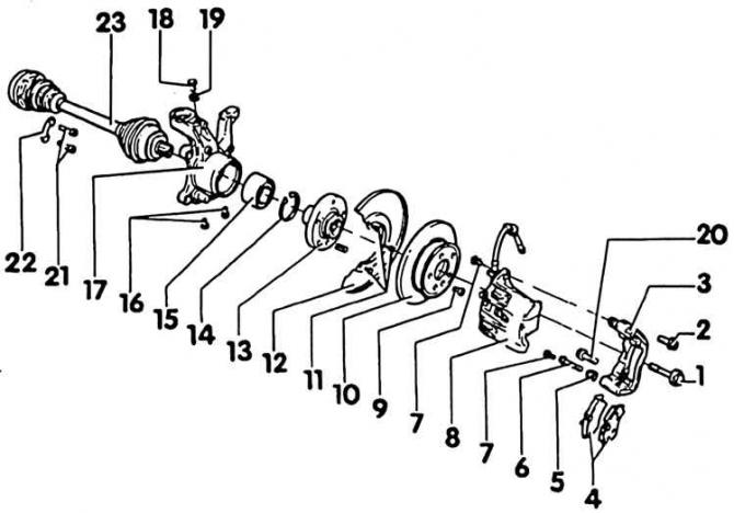
Hub and axle shaft


1. Bolt, 200 Nm; 2. Wheel bolt, 160 Nm; 3. Brake support; 4. Brake linings; 5. Protective cap; 6.…

1. Bolt, 200 Nm; 2. Wheel bolt, 160 Nm; 3. Brake support; 4. Brake linings; 5. Protective cap; 6. Guide fingers; 7. Screw, 35 Nm; 8. Brake mechanism housing; 9. Locking screw, 5 Nm; 10. Brake disc; 11. Screws, 8 Nm; 12. Protective fence; 13. Wheel hub; 14. Safety washer; 15. Wheel bearing; 16. Bolt, 16 Nm, M10x20; 17. Wheel bearing housing; 18. Bolt, 60 Nm, M12x 1.5x22; 19. Washer; 20. Bolt, 270 Nm; 21. Bolts, 70 Nm; 22. Backing plate; 23. Half shaft


Attention! When removing the axle shaft, the car must not be pushed from its place, since the lack of axial stress will damage the rolling element of the wheel bearing. If necessary, install an outer hinge instead of the axle shaft.


Removal


1. Support the upper steering knuckle.

2. Unscrew the screw securing the wheel hub to the axle shaft.

Attention! The screw is very tight, when loosened the car should stand on its wheels.


3. Place the front of the machine on jack stands.

4. Remove the lower engine compartment guard.
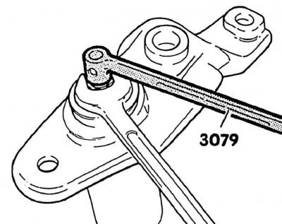
4. Remove the lower engine compartment guard.


5. Disconnect the screw connection between the wheel bearing housing and the lower axle joint.


6. Remove the shock absorber screw - connecting rod and stabilizer.

7. Unscrew the inner hinge bolts.

Automatic transmission


1. Disconnect the plug from the multifunction sensor.

2. Unscrew the rear rubber-metal support on the bracket of the mounted units (see subsection 4.2).

3. Press the axle shaft away from the flange.

4. Compress the shock absorber completely.

5. Remove the axle shaft from the wheel bearing housing. On cars with an automatic transmission, simultaneously push the engine – gearbox slightly forward.

Installation


1. Before installation, wipe the axle shaft splines and wheel hubs dry with gasoline (no oil or fat), and also remove any remaining preservative.

2. Install the axle shaft into the wheel hub and secure with the old screw. Do not tighten the screw.

3. Attach the half shaft to the gearbox. Tighten the internal synchronizer screws crosswise to 70 Nm. Don't forget the shims.

Attention! From 8/91 to 6/92, the internal synchronizers on the right and left were secured with different screws. Right half-shaft: screw M10x48, strength 12.9, head with internal hexagon. Left half-shaft: screw M10 x45, strength 10.9, head with internal hexagon.


4. When repairing, install only screws with a strength of 12.9. For cars up to 6/12, shorten the screws by 45 mm in order to provide access to the gearbox housing. Screws with a strength of 10.9 should never be tightened to a torque of 70 N·m.

5. Tighten the rear rubber-metal support on the attachment bracket to a torque of 45 Nm.

6. Connect the plug of the multifunctional sensor.


7. Install the shock absorber – connecting rod bolts and tighten to 160 Nm.

8. Install the lower axle joint onto the wheel bearing housing and tighten with a new nut to 110 Nm (manual transmission) or 55 Nm (automatic transmission).

9. Install the lower engine compartment guard.

10. Remove the car from the jackstand.

11. Unscrew the axle screw and screw the half shaft with a new self-tightening screw to a torque of 200 Nm.

Attention! The car must be on its wheels.

This article is available at russian, bulgarian, belarusian, ukrainian, serbian, croatian, romanian, polish, slovak, hungarian
The text has been checked: Orlov Dmitry

Share information:

Previous articles
Shock absorber — removal and installation
Upper steering knuckle support
General information about the front suspension
Front suspension — design description
Next articles
Disassembly and assembly of front drive axle shafts
Rear suspension — design description
General information about the rear suspension
Removal and installation the rear shock absorber
Checking the rear shock absorber
Rear shock absorber coil spring


Similar articles from other manuals for VW cars:
Removal and installation front wheel drive shafts Passat B2 (1981-1988)
Front drive shafts Golf 3 (1991-1997)
Constant velocity joint axle shafts Polo 3 (1995-2003)
Checking the oil level in the main gear of the front axle Touareg 1 (2002-2006)
Removal and installation of rear axle ABS system components… Tiguan 1 (2007-2015)
Wheel Drive Shafts — Design Description Sharan 1 (1995-2000)
General description of drive shafts Caddy 3 (2003-2010)
Link to this page in different formats


Visitor comments


No comments yet


How much will 26 + 48 =


Transporter T4 
  • General information
  • User manual
  • Maintenance
  • Power unit
  • Engine repair
  • Ignition system
  • Lubrication system
  • Cooling system
  • Fuel system (petrol)
  • Fuel system (diesel)
  • Injection system (petrol)
  • Exhaust system
  • Transmission
  • Clutch
  • Car gearbox
  • Chassis
  • Car suspension
  • Steering
  • Brake system
  • Wheels and tires
  • Body
  • Exterior
  • Interior
  • Doors and windows
  • Heating system
  • Electrical equipment
  • Equipment and devices
  • Lighting and signaling
  • Power devices
  • Electrical circuits
Transporter T3 
  • General information
  • Maintenance
  • Petrol engines
  • Engine repair
  • Lubrication system
  • Cooling system
  • Power and exhaust system
  • Carburetor 34 PICT
  • Carburetors 2E3 and 2E4
  • Fuel injection system
  • Ignition system
  • Diesel engines
  • Engine repair
  • Lubrication system
  • Cooling system
  • Power and exhaust system
  • Transmission
  • Clutch
  • Car gearbox
  • Chassis
  • Front suspension
  • Rear suspension
  • Steering
  • Brake system
  • Body
  • Body and interior elements
  • Doors, locks and windows
  • Electrical equipment
  • Lighting system
  • Equipment and devices
  • Power devices (diesel)
  • Power devices (petrol)
  • Wiring diagrams (diesel)
  • Wiring diagrams (petrol)
VWmanual.ru © 2016-2026 | Mobile version | News and articles | Sitemap: EN BG BY UA RS HR RO PL SK HU | Write message | Site search
Passat B2 • Passat B3 • Passat B4 • Passat B5 • Passat B6 • Golf 1, diesel • Golf 1, petrol • Golf 2, petrol • Golf 2 • Golf 3 • Golf 4 • Golf 5 • Polo 3 • Polo 4 • Touareg 1 • Tiguan 1 • Sharan 1 • Transporter T3 • Transporter T4 • LT 28 • LT 2D • Beetle • Caddy 3 •
Our website uses cookies to ensure functionality and convenience.